Products
Conveyors
GME has developed several systems for material handling, necessary for logistic of industrial production lines. Learn more about our automated conveyor solutions below.
The Skid is an essential element of a plant’s logistics. It must guarantee the position of all parts and roller tables proper functioning during the transfer to the next operation. In addition, it must ensure precise product positioning in robotic stations or in the skid exchange stations.
Construction within the permitted tolerances and the correct manufacturing process guarantee a stable behavior throughout the process path. Skid models can be developed for simple material handling applications, or for geometry in welding operations (geo-skid).
Technical Features
- Approximate maximum dimensions: 8000 x 3000 x 600 (mm) (L x W x H)
- Approximate maximum load per skid: 4000 kg
- Permissible temperatures: From -10°C to 300°C
- Surface treatment: Painting/Galvanized
Variants
- Stainless steel, RFID tag, product locks, vibration or temperature normalization after soldering
Also known as Power Roller Beds, they are the basis of logistics based on skid conveyor systems.
Designed to be modular, simple and with high operating availability, the system is suitable for skid transport and processing. Highly flexible, they can be installed on floor-mounted racks, in elevators, shuttles and other equipment common to skid transport lines.
With a standardized design, pattern variants can be created according to the process particular requirements.
Technical Features
- Approximate maximum dimensions:: 8000 x 3000 x 2000 (mm) (L x W x H)
- Approximate maximum load per skid: 4000 kg
- Transport speeds: from 15 to 100 m/min
- Approximate Cadence: 90 cycles per hour
- Rollers driven by timing belts or metal chains
- Vulcanized or steel rollers according to the process requirements
- Surface treatment: painting/galvanizing
Variants
- Number of rollers per table, stainless steel structure, high temperature chain traction, protective covers to enable work and/or operators passage, variable roller speed, side guides, pneumatic safety stop, pneumatic stop position centering device.
Equipment used in skid transport lines to make curves according to the layout. They can also be used to reverse the orientation of the skid/body assembly on a skid transport line. Roller Turntables can be constructed with either concentric or eccentric swivel axis.
Technical Features
- Approximate maximum dimensions: 8000 x 8000 x 2000 (mm) (L x W x H)
- Approximate maximum load per skid: 4000 kg
- Approximate transport speeds: maximum 50 m/min / min
- Turning Speed: 15 m/min (6 to 8 seconds)
- Rotation: up to 360°
- Approximate Cadence: 90 cycles per hour
- Motorized rollers by toothed belts
- Vulcanized or steel rolls according to the project requirements
- Surface treatment: Painting/Galvanizing
Variants
- Concentric or eccentric rotation, stainless steel structure, high temperature chain traction, protective covers to enable work and/or operators passage, variable roller speed, side guides, anti-fall system, on-board or panel driver.
This device is used to “transfer” the skid from one line to another one. This kind of application is very useful when it is necessary to change production flow or sequence, for example in overhead buffers (where several lines are located in a parallel way).
Technical Features
- Transport height: from 400 to 800 mm
- Payload: from 20 to 2,000 kg (up to 4,000 kg for skid handling system)
- Handling speed: up to 24 m/min for optimal cycle time
- Roller conveyor, turntable, chain conveyor (or telescopic forks) mounted on the same system
- Surface treatment: painted or galvanized
Variants
- Covers, adjustable sensor holders, barcode positioning system, RFID reader/recorder, energy gathering by busbars or non-contact induction instead of drag chain.
The Cross Transfer & Pop-Up Tables systems are used when your flow is divided into multiple flows or merged into another flow. The load is transferred from one pop-up table to another via plastic or metallic chains, allowing better cycle time than the Shuttle Transfer, in addition to product accumulation.
Pop-Up Lift Tables, or uncoupling tables, are essential when your flow must be accumulated and deflected at 90°. The skid or pallet is transferred from a chain conveyor to a roller conveyor or vice versa.
Technical Features
- Transport height: from 400 to 800 mm
- Stroke: up to 50 meters
- Payload: from 20 to 2,000 kg (up to 4,000 kg for skid handling system)
- On board: a roller conveyor, chain conveyor or telescopic forks
- Surface treatment: painted or galvanized
Variants
- Dual backup drive, covers, adjustable sensor holders, barcode positioning system, RFID reader/recorder, energy gathering by busbars or non-contact induction instead of drag chain.
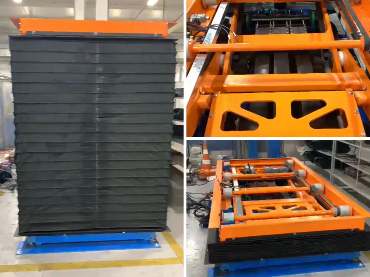
Column Elevators are used when production logistics need to change levels, allowing loads to be moved vertically. In cases where the Skid/EOM transport system is deployed on multiple levels, the elevators allow reliable vertical movement of the load.
Technical Features
- Lift stroke: From 400 to 20,000 mm
- Payload: From 20 to 5,000 kg
- Lifting speed: From 10 to 60 m/min
- Handling height in low position 400 mm
- On-board roller conveyor
- On-board chain conveyor
- On-board EOM conveyor
- Powered roller table
- Telescopic forks
- Electrically or pneumatically powered drive
- Lifting principle: Steel cables, belts or chains
- Surface treatment: Painted or galvanized
Variants
- Plastic chain, metal chain, dual drive to allow reversion, covers, adjustable sensor holders, barcode positioning system, RFID reader/recorder, energy gathering by busbars or non-contact induction instead of drag chain, safety lock.
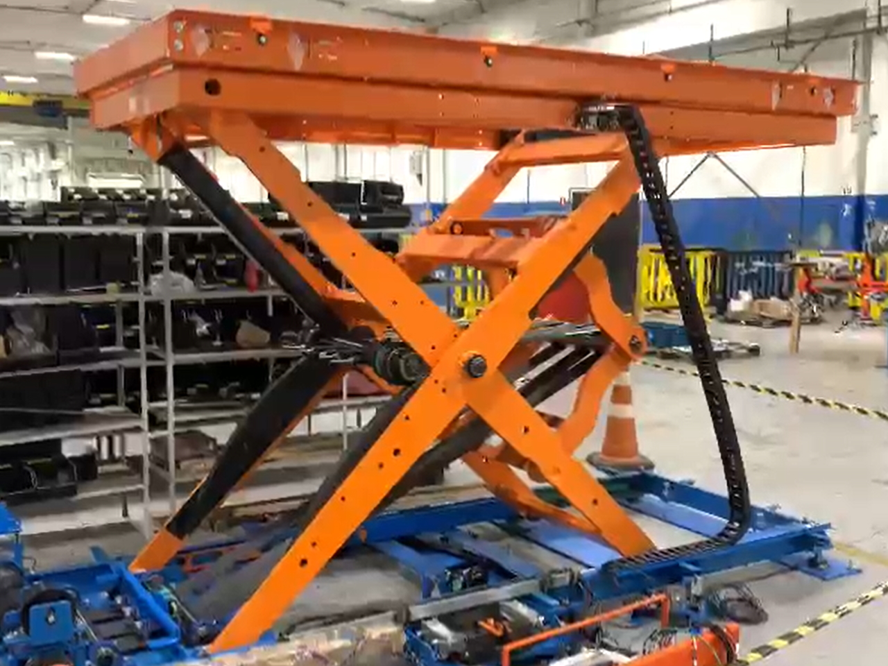
Scissor lift tables, or pantograph tables, are suitable especially when your flow needs a level change on the same floor. Pantograph lifting tables can be applied in automated or manual process lines.
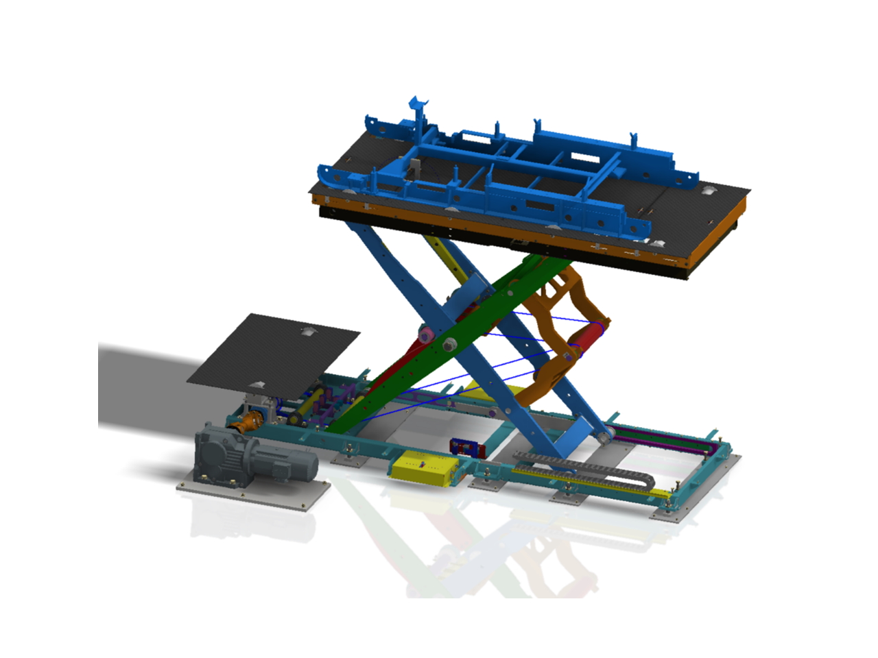
Technical Features
- Lifting stroke: from 400 to 2,000 mm
- Payload: up to 3,000 kg
- Lifting speed: From 4 to 20 m/min
- Lowest conveyor level: 400mm
- On-board conveyors: roller table, chain conveyor or telescopic forks
- Drive power: hydraulic or electric
- Surface treatment: painted or galvanized
Variants
- Covers, adjustable sensor supports, tubular safety grid (the entire vertical elevator length), dual motorization, positioning system by encoder or sensors, RFID recorder/reader, safety lock.
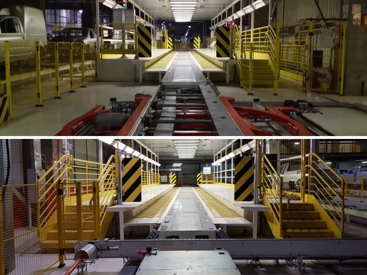
Designed to slowly move the product at a constant speed facilitating operators, where both the product and the operators can be transported together.
- Made of steel or plastic material, they guarantee ergonomic and safe conditions for manual operation;
- Ideal for final assembly or manual finishing lines.
Technical Features
- Conveyor length: up to 150 meters
- Useful load per work stage: Maximum 4,000 kg
- Speeds: from 0.5 m/s to 10 m/s
- Cycle time: as required
- Surface treatment: Painted structure. Conveyor parts according to demand (painted, galvanized, in-line, etc.)
Variants
- Pit, lids, safety fences, variable speed, call buttons, HMIs, barcode readers, lighting tunnel for visual inspection, variable operating height according to ergonomic needs.

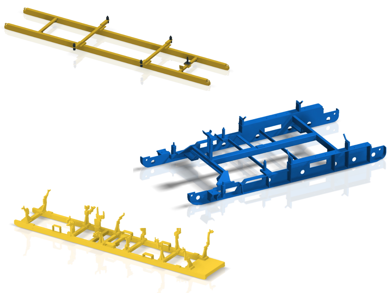
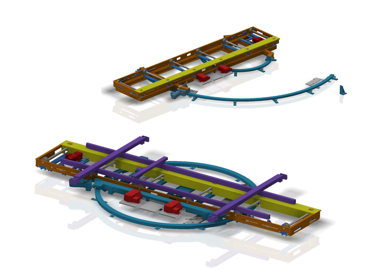
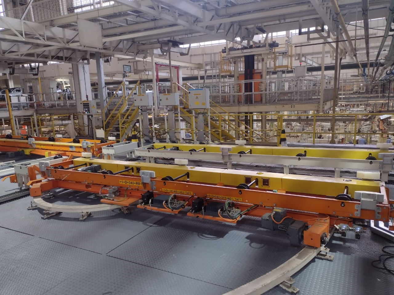
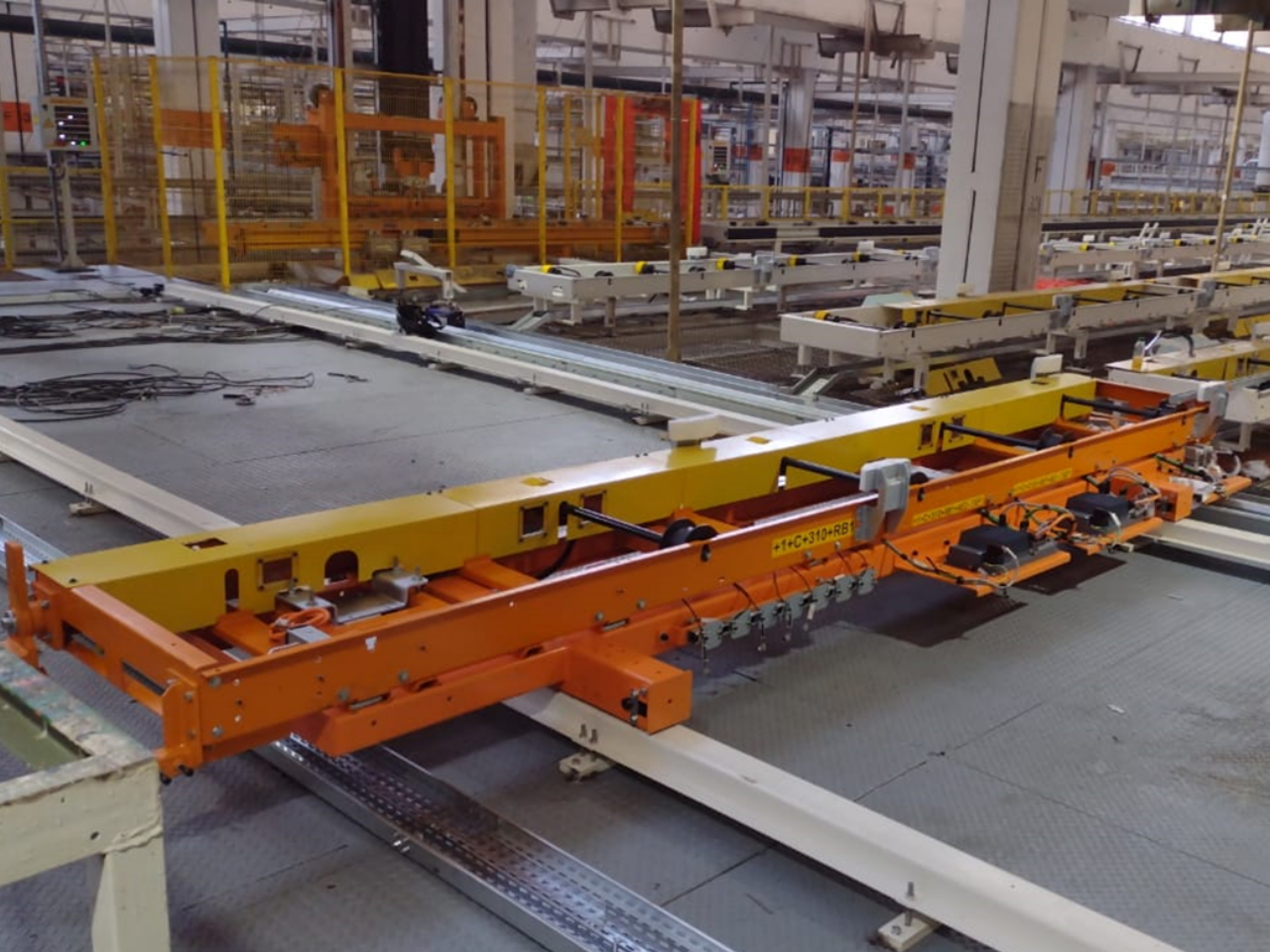
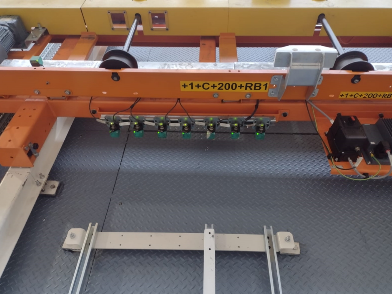
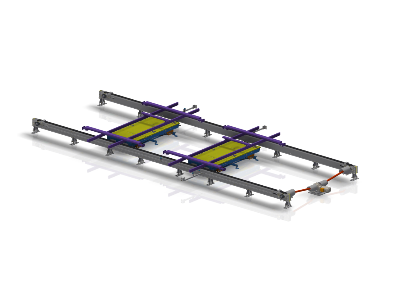
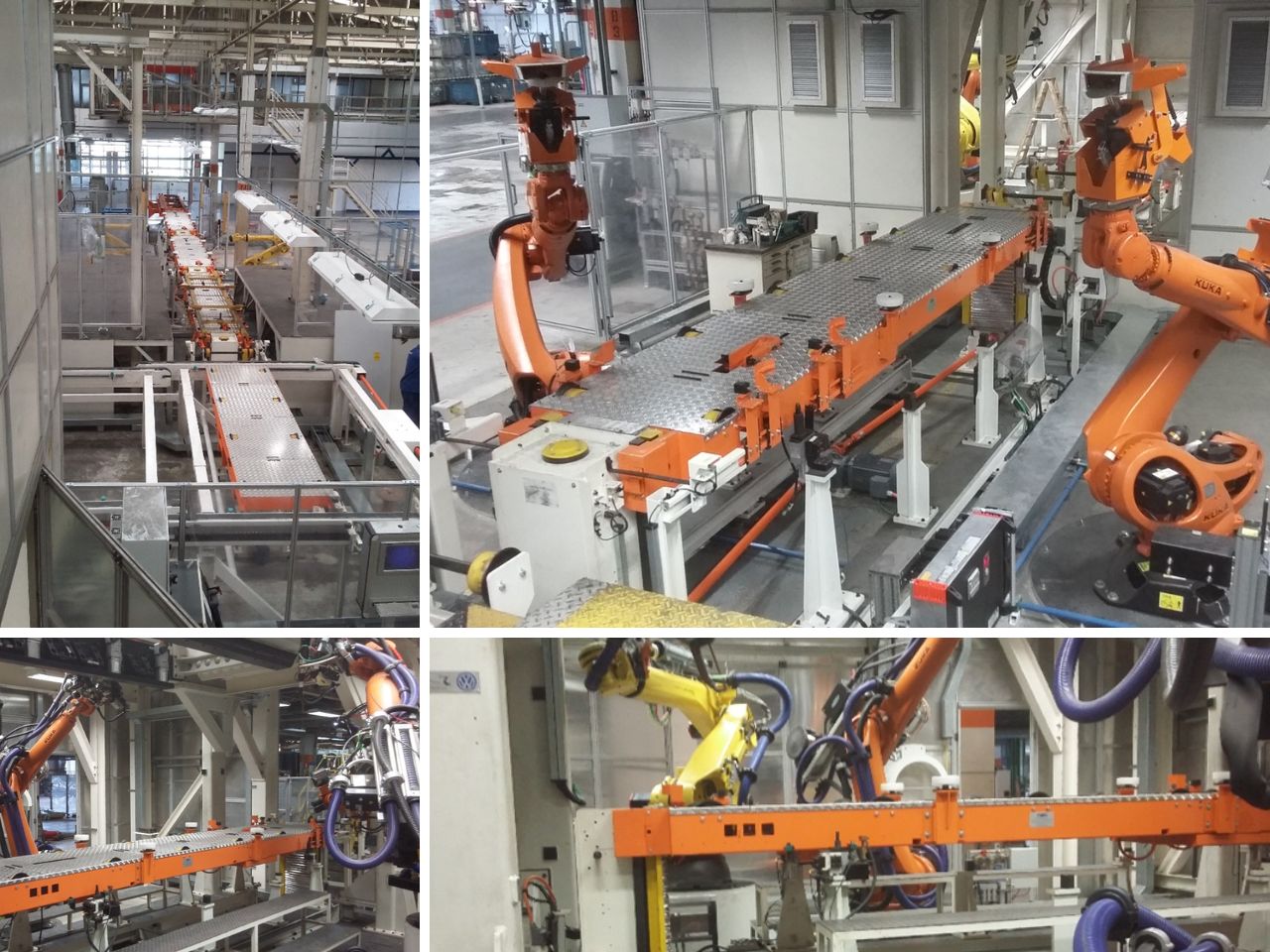
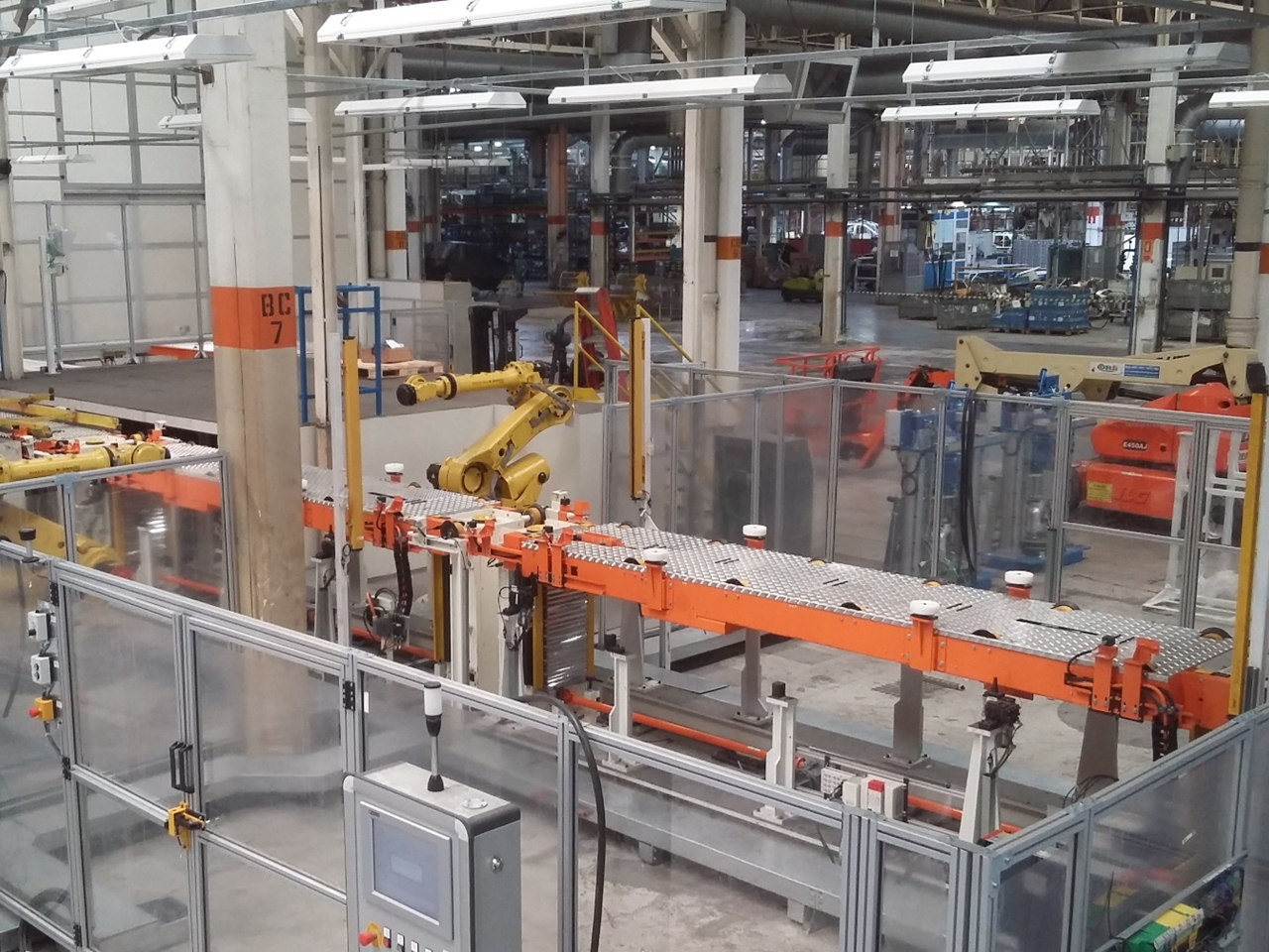
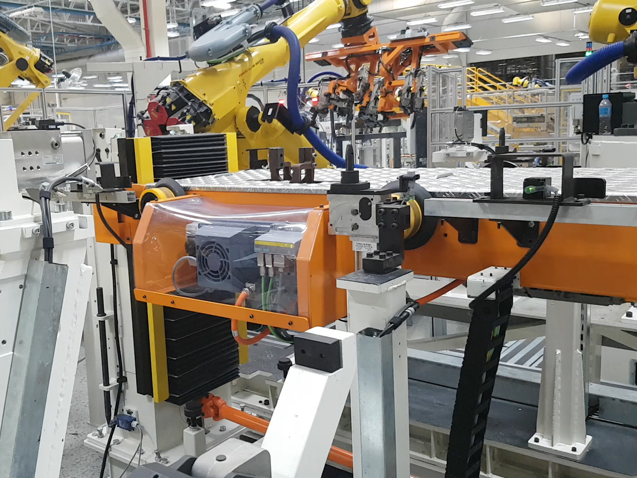
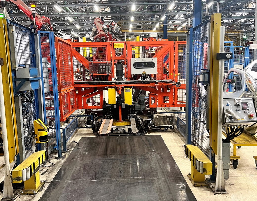
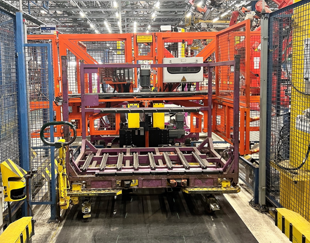
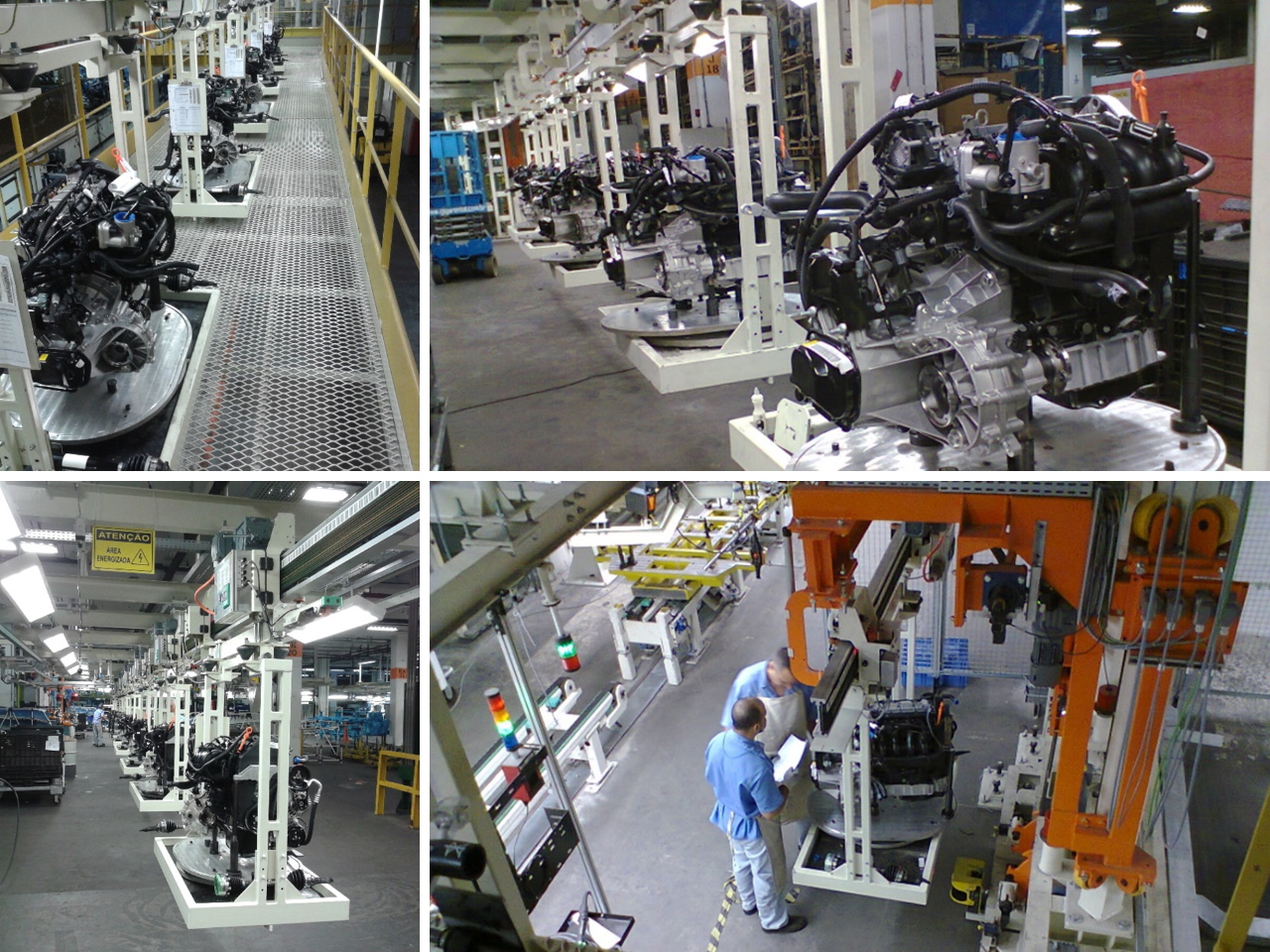
Lifter Roller Tables
GME Lifter Roler Tables allow the skid/body set to be positioned in a precise way in each operation of the line. The tables are equipped with two basic systems to carry out this task:
- Transfer System
- Lifting System
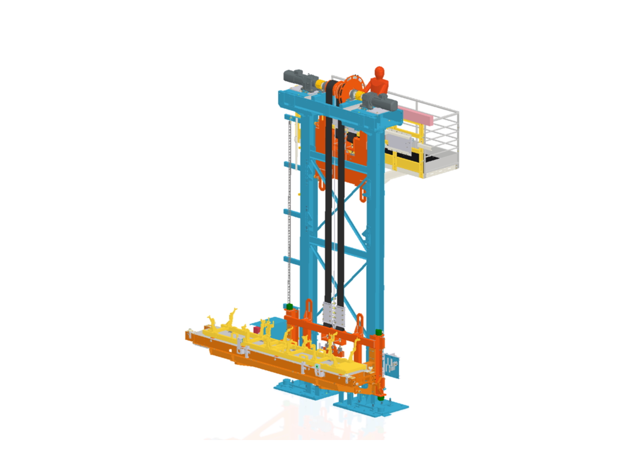
The lifting system is composed of two parallel towers which hold ball screws synchronized via a coupled cardan. The lifting set is dimensioned according to the load needs and speeds required in the process.
The transfer system is based on guide wheels, enabling to reach high speeds (up to 120 m/minute) when the skid is transferred from the previous operation to the next one.
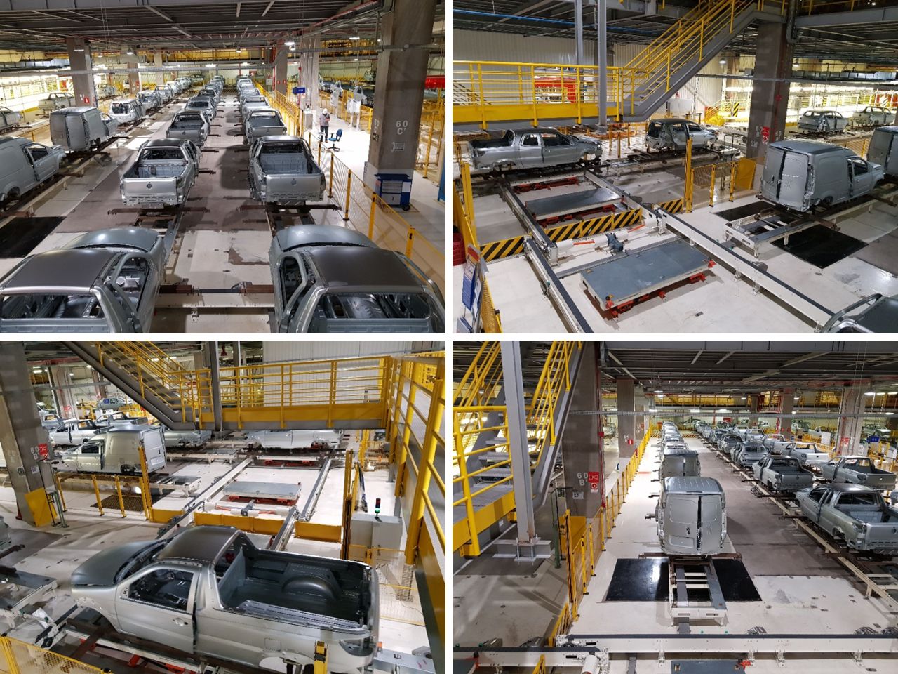
The system is adaptable to different skid/body sizes according to the installation requirements, making it suitable for different stations and applications.
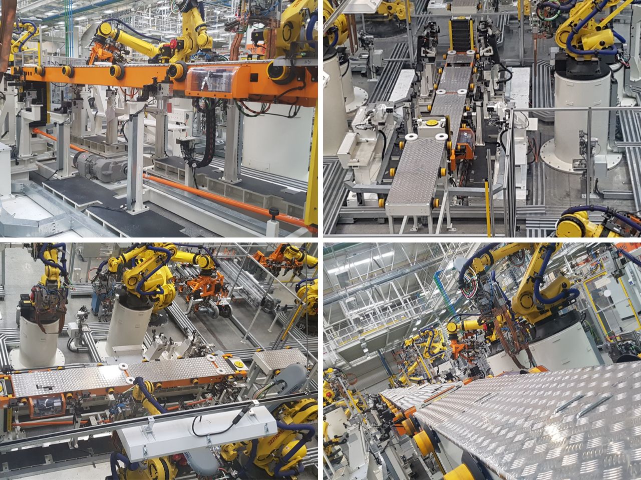
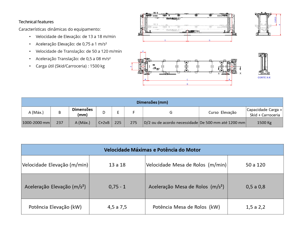
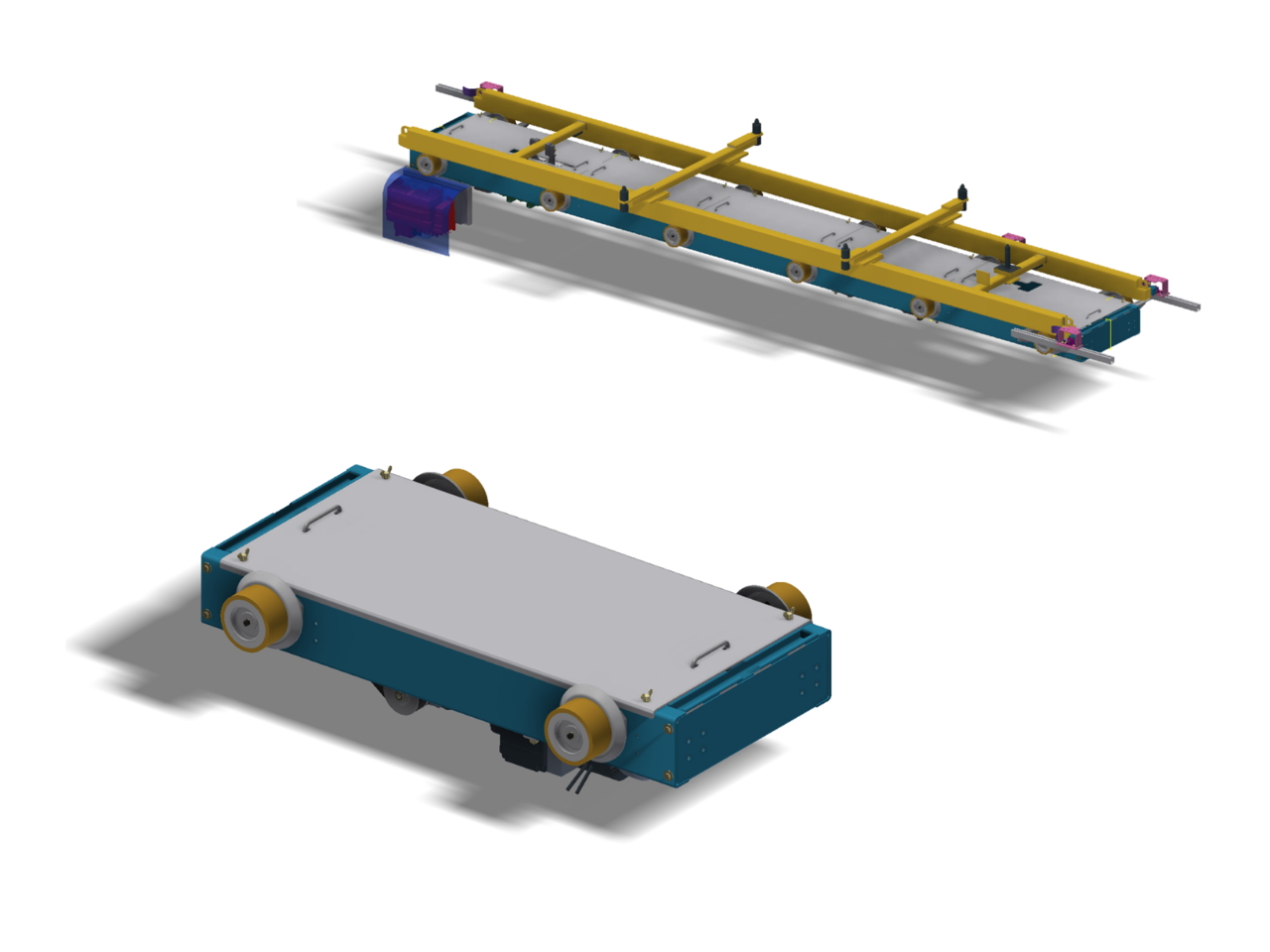
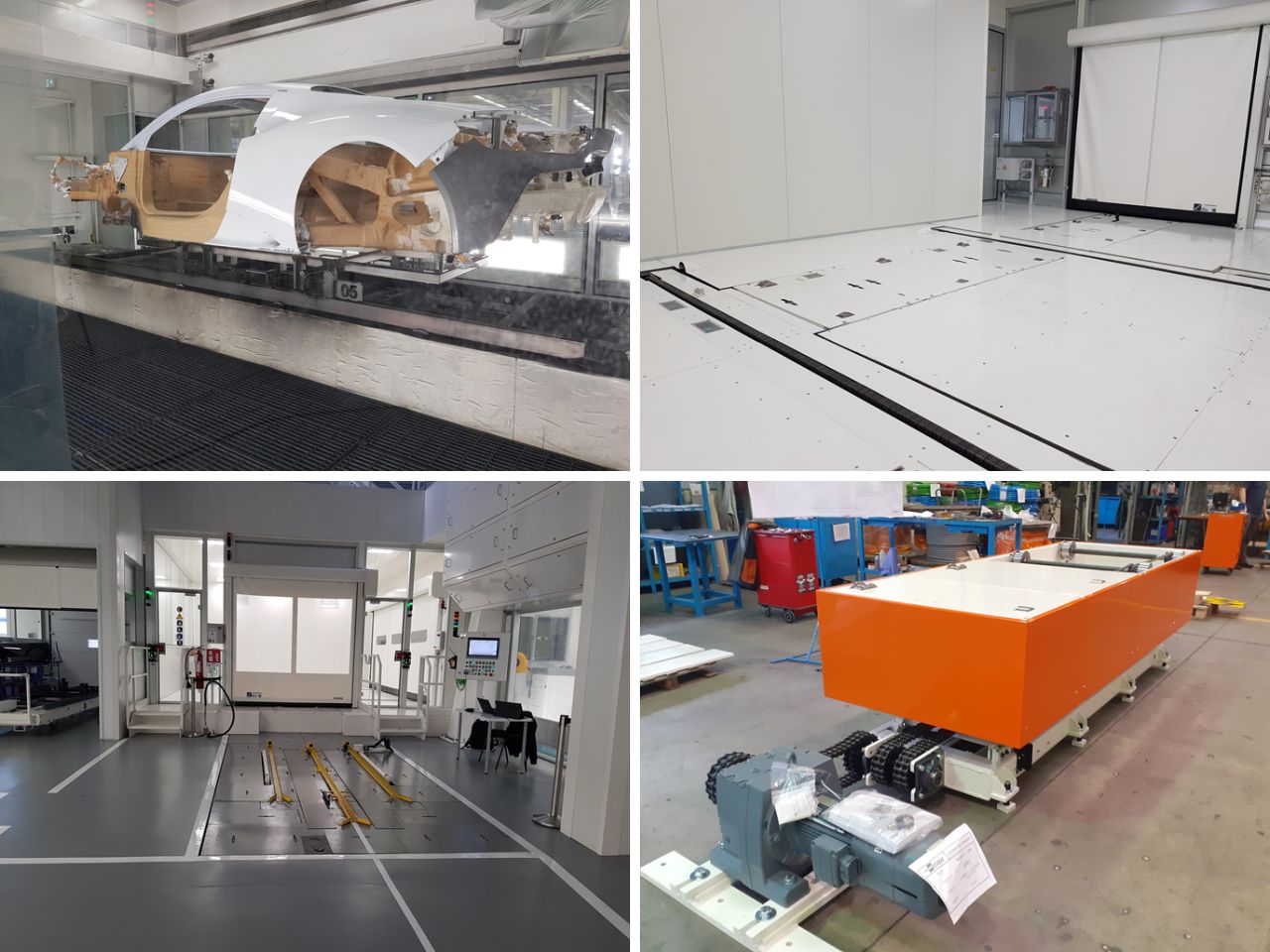
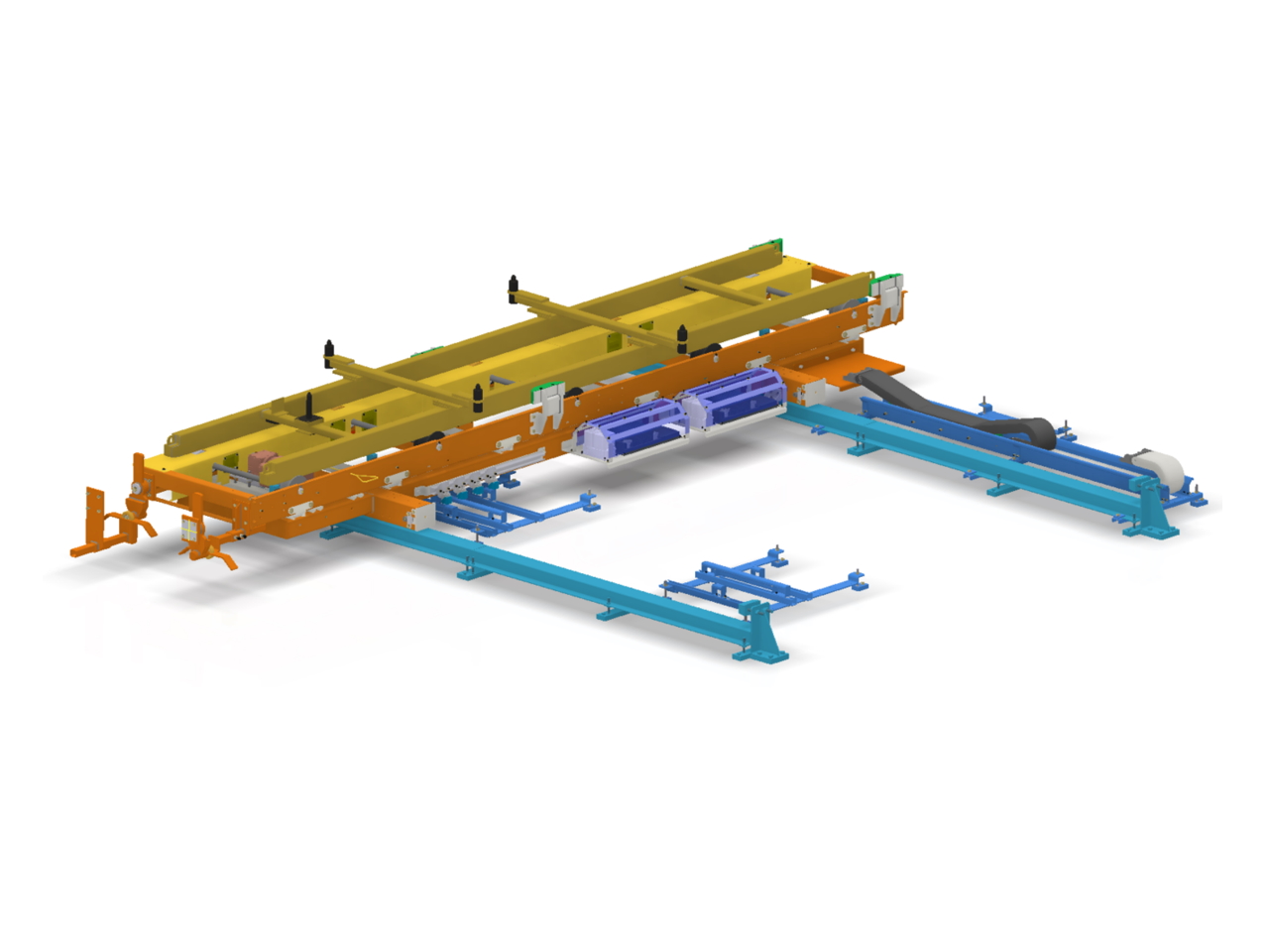
Main Features
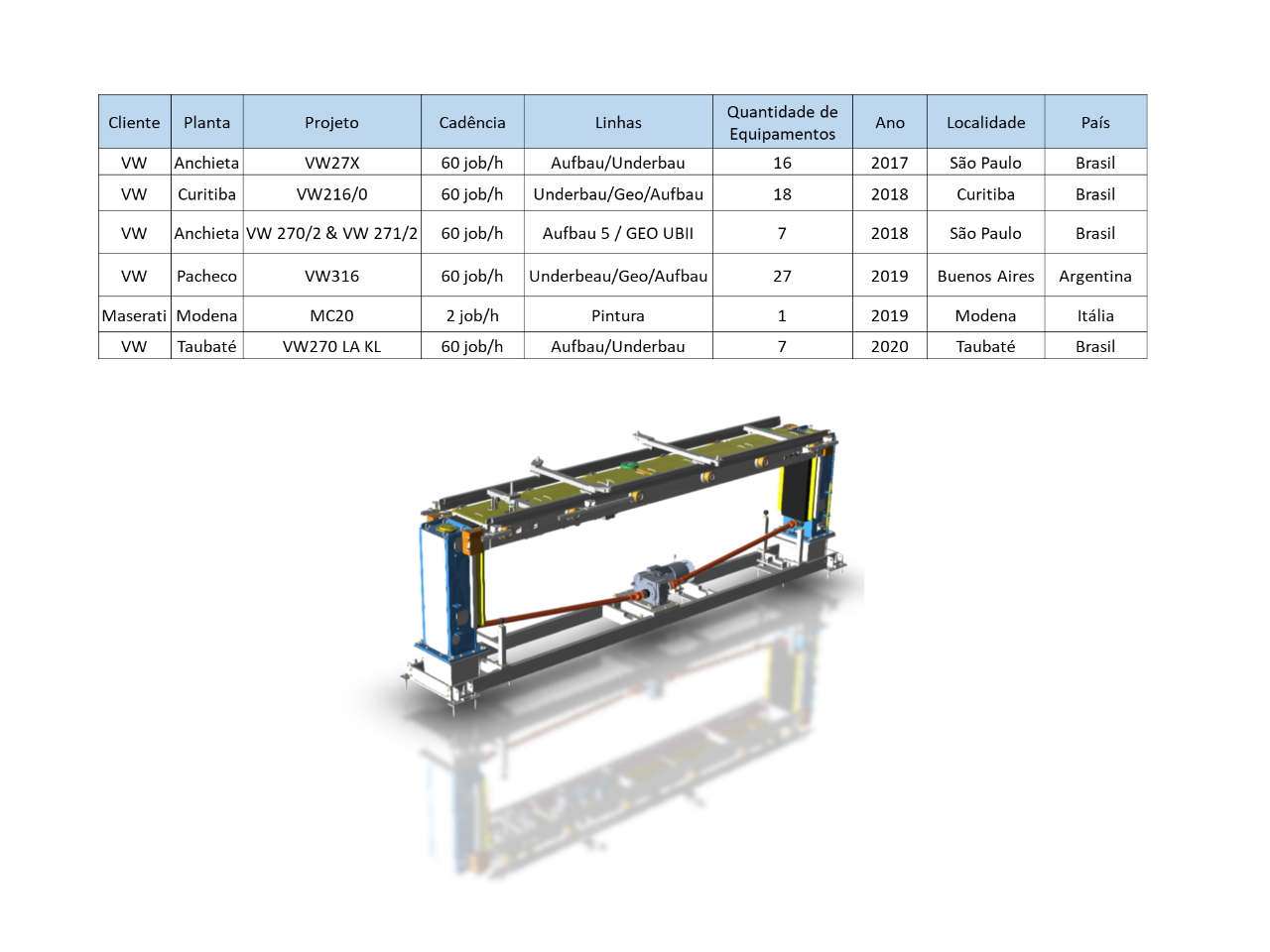
Based on GME’s technical expertise, combined with the experiences exchange and performed tests, considerable improvements were implemented in the product to increase the equipment performance. GME has installed around 80 units in Brazil, Argentina and Italy since 2017.
Features:
- Equipment mounted on a “single base” (single reference system) that allows quick assembly in an industrial environment
- The equipment is delivered assembled and regulated, requiring only adjustments for installation and operation. No laser measurement is required for installation
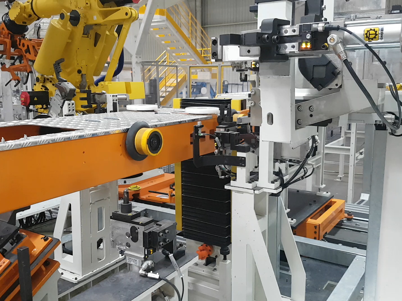
- Dual guide system that increases the life cicle of lifting components. The lifting towers have a linear guide system which works together with the ball screw to transmit the lifting motion. On the other hand, roller tables have a steel rollers system that guide the table in vertical movement. In this way, the table guidance system absorbs forces coming from decelerations generated by the skid/body set in the general dynamics of equipment operation
- The equipment is integrated with commercial components, allowing the replacement of equivalent components if necessary
- Dual belt system on the drive power transmission and on the roller belts 2-3
- Skid centering system to centralize the load and Safety Stopper to protect nearby manual stations
- The equipment movement is controlled by motor reducers in closed mesh (using encoders) or through servomotors, to obtain higher speeds
Logistic
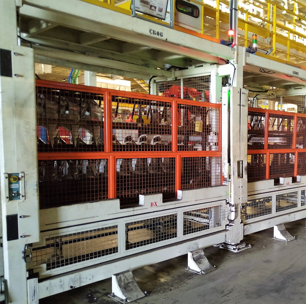
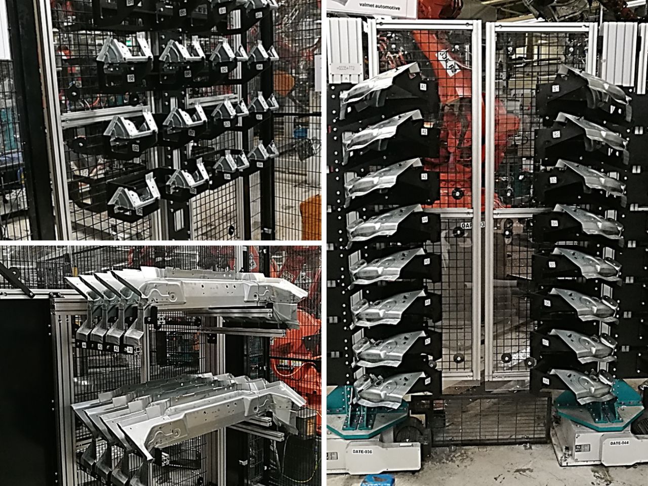
Together with the EFORT WFC Group, GME has developed various logistics systems required for parts loading/unloading in production lines. Logistics solutions need to be precise, reliable, easy to handle and simple maintenance to meet the requirements of highly automated production plants.
Rotating load/unload systems for quick changeover of full versus empty racks during production (no loss of cycle time).
The bay has 2 types of movement: the first one is a vertical movement (to separate the rack from the trolley that transports it) and the second one is a rotating movement (for rack changing).
Operators’ loading/unloading operations are facilitated by the roller guides, which allow quick rack replacement. When the rack is on the inner side of the line, it is always referenced through a centering system, in order to guarantee the necessary repeatability required by the robot for automatic loading/unloading operations.
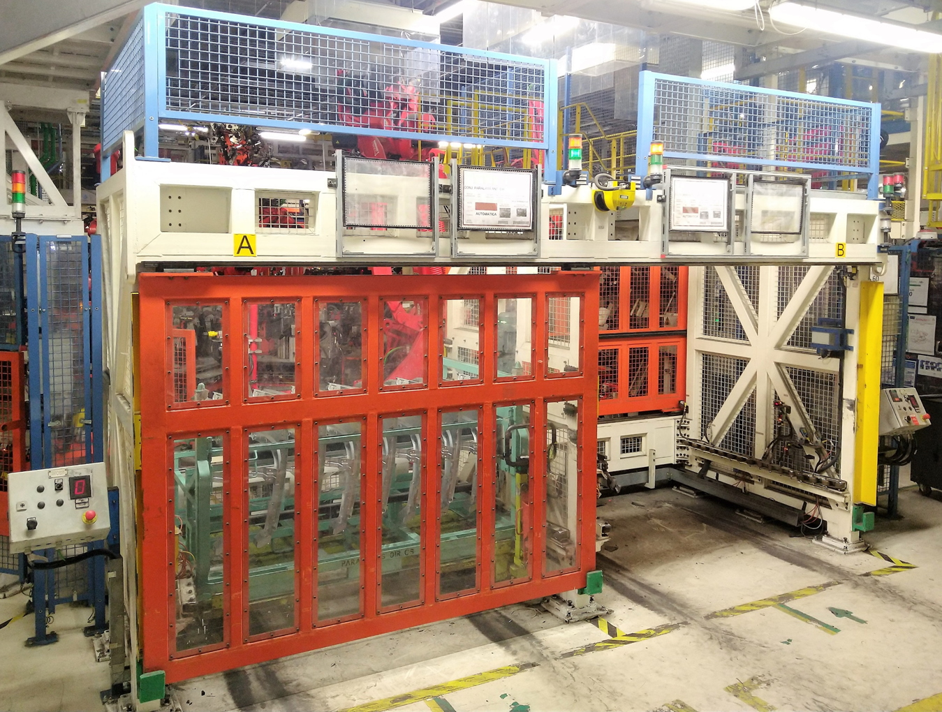
Static system with linear movement for quick rack changing (full vs empty) during production (no cycle time loss).
The safety doors alternately open and close in order to keep the robot’s working area separate from the operator’s area, who performs rack loading/unloading operations on the opposite side. In this way, safety conditions are guaranteed throughout the cycle.
Loading and unloading systems with vertical movement and rack recirculation. Fast replacement of full versus empty racks during production, with no cycle time loss and space saving on the loading side. This is a suitable solution where space on production lines is limited.
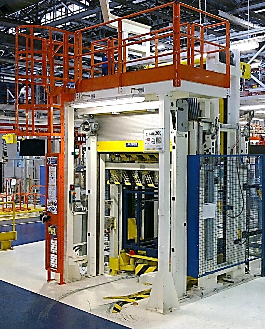
Systems with vertical linear opening (double door), overhead buffer and dedicated platform for maintenance access. Racks loading and unloading is made with a forklift, without stopping the line and avoiding any impact on production.
Simpler and more compact solution, particularly suitable for very heavy racks that are difficult to handle manually.
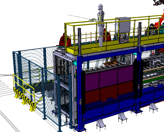
Vertical buffer with manual feeding and automatic consumption, with automatic rotating movement. This system is proposed as an alternative to the classic APC (Automatic Pallet Conveyor), reducing the space occupied on the line side and reducing costs significantly compared with a traditional conveyor.
Hemming Systems
GME’s Table Top technology is based on an automatic system, including a set of electromechanical elements that compose the hemming machine. This system can be used for both steel and aluminum parts. Table-top hemming technology offers better product quality, with less space requirements and reduced cycle time.
The robotic roller hemming system consists of a standard industrial robot, integrated with a hemming head, offering a very flexible solution. The Hemming head consists of a central body, with guides and rollers that are designed according to the customer’s product geometry. It is a simpler system than the Table Top version (more suitable for lines with high production volumes), offering greater flexibility. Roller hemming technology can be used for both steel and aluminum elements.
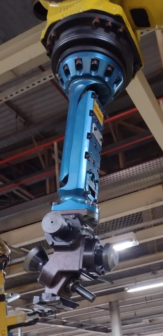
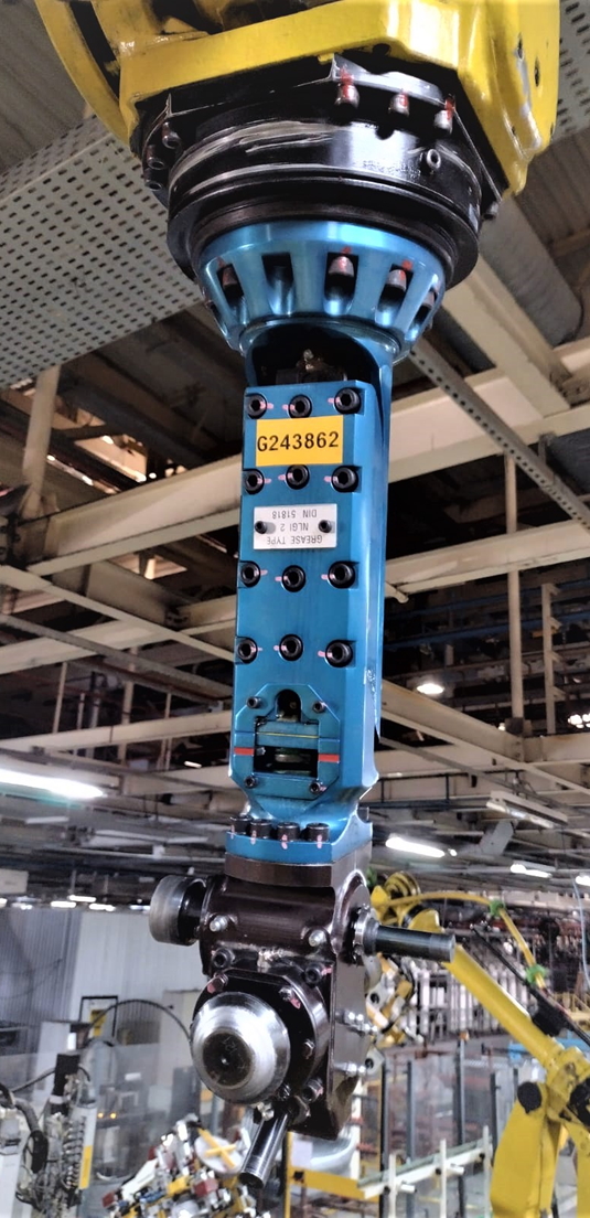
STD GME Roller Hemming Heads have a combination of high resistance rollers, developed according to customers’ product features and process requirements.
Simple to maintain, easy to install and adaptable to all robot models used for these processes.
In addition, the hemming rollers are moved directly due to friction with the part they come into contact with, avoiding the need for a power supply. This feature prevents the use of external equipment, reducing the occupied space and costs.
STD GME system for perimeter flaps angle correction, when it presents an excessively open angle. This system aims to reduce the opening angles that exceeds the acceptable limits for the Table-Top hemming system, generating a bending radius to maintain process tolerances. It is an electro-pneumatic system, suitable for both steel and aluminum elements, providing a higher product quality, suitable for production lines with limited space and high production volume.
The pre-bending operation can also be performed using a dedicated hemming roller, following the same principles as the electro-mechanical unit.

STD GME system for folding flaps in difficult area (product sharp angles). This system aims to prepare these regions for roller hemming or table top hemming processes. It is an electro-pneumatic system, suitable for both steel and aluminum elements, offering a better quality end product, suitable for production lines with limited space and high production volume.
GME is always looking for new solutions and technological advances available on the market to continuously improve lines and equipment development processes. Based on this vision, we have acquired a software that directs our team to a better performance in the development of hemming devices, such as Table-Top and Roller Hemming.
This software defines and optimizes the hemming operation easily, identifying and simulating the deformations in the product folds and stresses generated in the design phases, also creating the tool geometries required for the simulation. As a result, roller, tooling and table-top hemming processes can be efficiently designed. Depending on the product development process stage, the software supports two application cases, initial and advanced hemming analysis.
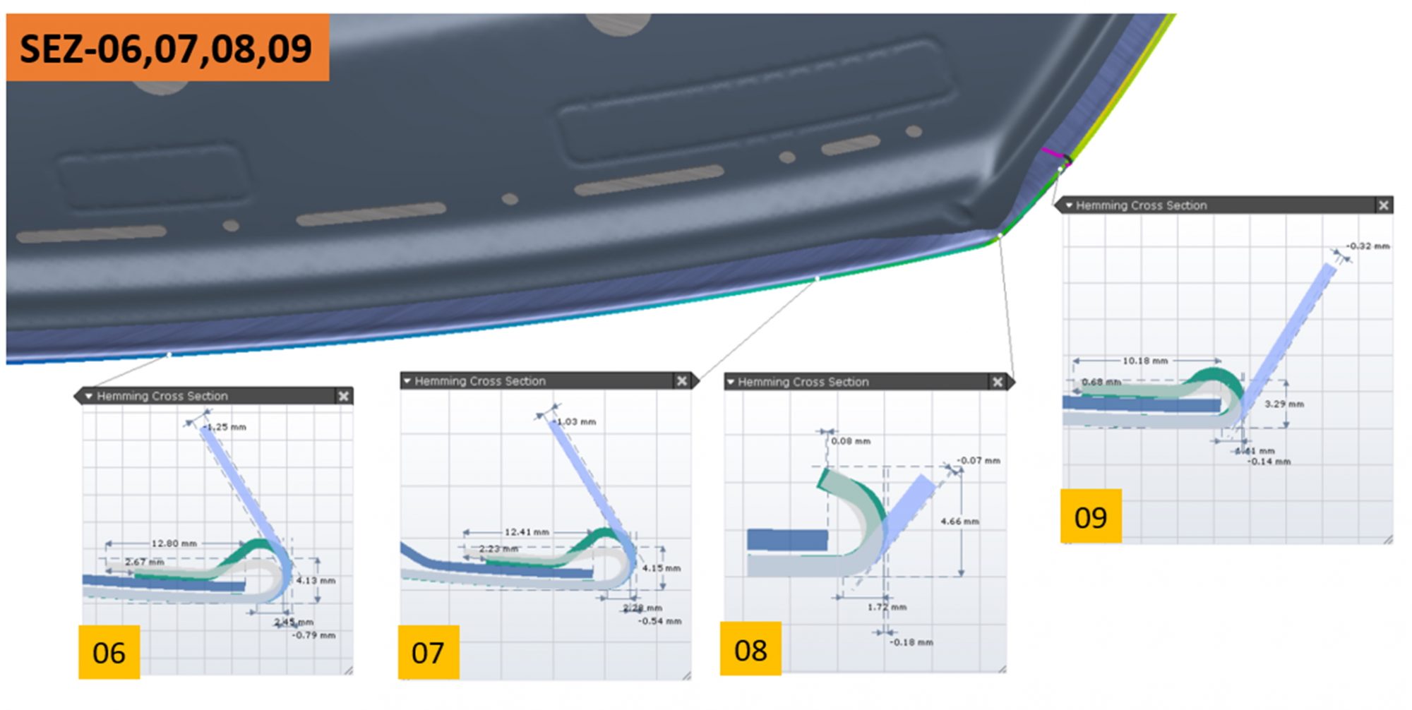
Benefits
- Definition of hemming processes to meet quality and cost requirements
- Early feasibility studies and final validation
- Identification of typical hemming defects
- Prediction of elastic recoil on the assembled set after hemming process
Key Features
- Support for roller, tooling and table-top hemming
- Early evaluation of various hemming concepts – initial hemming application case study
- Final validation of the hemming concept – application case study of advanced hemming
- Definition of tool geometry and kinematics
Main Features
- 45° hemming tool, working perpendicular to the flange
- 90° hemming tool, working perpendicular to the flange
- Electromechanical system
- Low number of components
- Easy maintenance
- Hemming cycle time (excluding parts loading and unloading): from 18sec to 33sec, depending on the system (with or without servo motor) and customer’s product typology
- Plate press: pneumatic or electromechanical actuation
- Units installed worldwide: 640
- Highest production capacity reached per unit: 5,500,000 (doors)

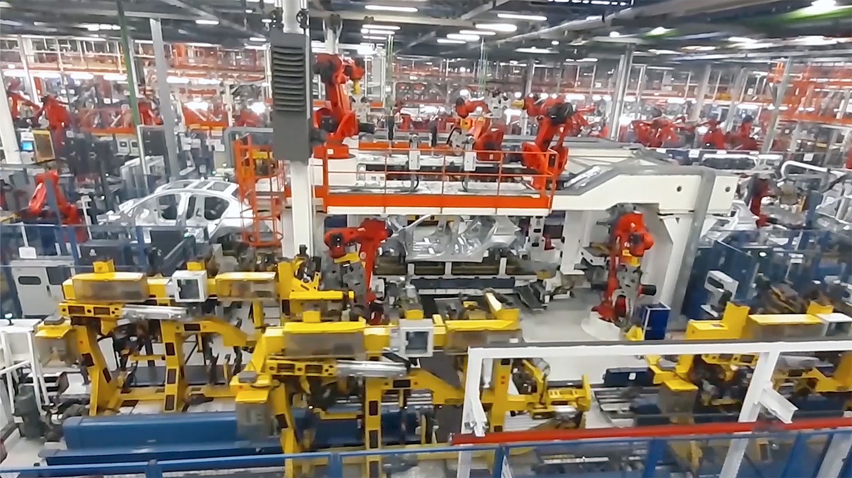
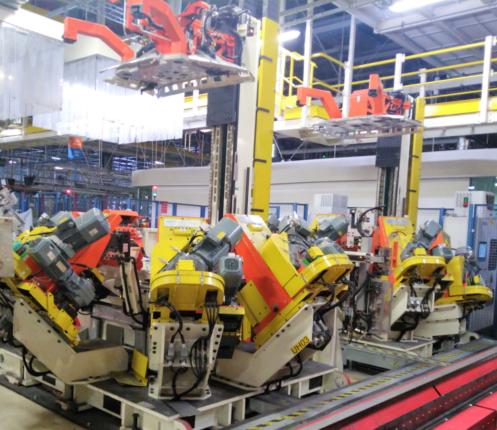
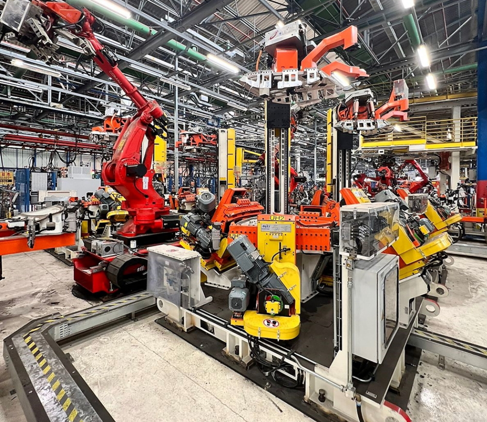
Geo Framing (CUBO)
Geo Framing is one of the most important and crucial operation within the whole body shop, where underbody, body sides and cross members are welded together. GME, together with the Italian Subsidiary OLCI Engineering, developed a new patented solution named “CUBO”, because of the shape which reminds the homonymous geometric figure.

Main Features
- Flexibility up to 4 models (due to area width limits, usually 20 meters maximum)
- Very high repeatability guaranteed by pneumatic locking systems along the jigs and the closed frame
- 10-second model change (during skid transfer from the previous operation to the next one), allowing high production rate in random mix mode
- Production capacity up to 60 JPH
- High weld spots density (up to 12 robots), due to the very precise offline programming
- Overhead robots are installed on a gantry (completely isolated from the framing station) to prevent product final quality from vibrations (caused by robots movement) during spot welding
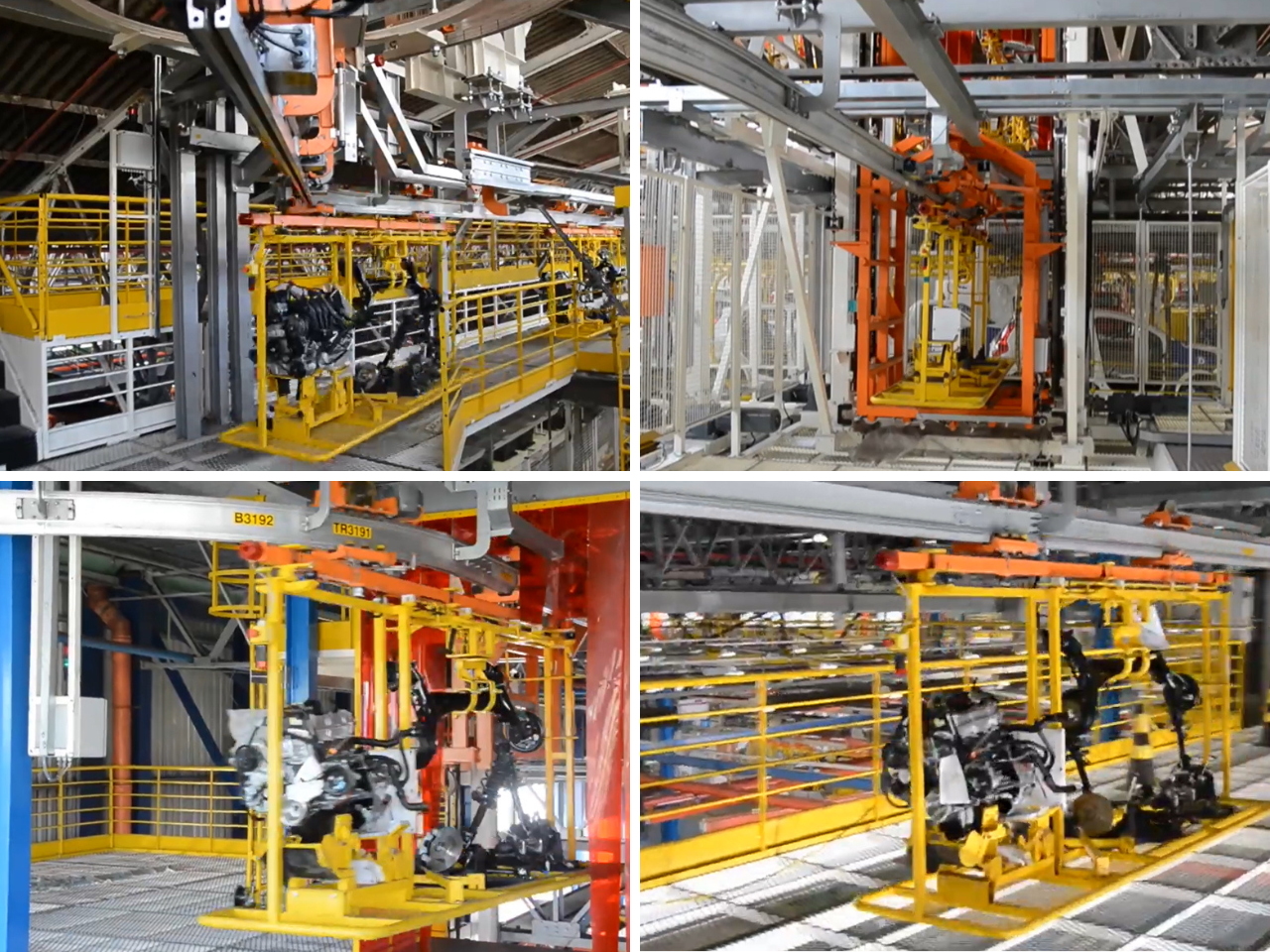
EOM Transport Systems
EOM (Electric Overhead Monorail) transport systems, also called EMS (Electric Monorail System), basically consist of a aluminum overhead rails system on which individual motorized trolleys are moved. Each trolley has its own control box. They are independent of each other in terms of movement, with the power supply and control are performed through induction or contact buses, fixed to the rail system. Transit control and management are performed centrally through a PLC.
This system was specially developed for situations where fast and intelligent transport over long distances is required (including transport between different plants or buildings), without obstructing access roads and corridors.
Line detours, elevators, translation carts, rotating detours, among others, can be added to the basic transport system, ensuring extreme versatility to the system, allowing the commonality of paths and the direction of loads, which guarantees that each load is present exactly on time and at the required cadence in the process.
Among the main sectors and applications, we can mention the automotive industry, for instance the movement and accumulation of bodies, the feeding and accumulation of parts and components (sides, doors, wheels, etc.) on welding and final assembly lines.
Main Advantages
- Silent and vibration-free transport
- High transport speeds
- Traceability and selectivity of loads
- Transport without environmental contamination (oil, grease, dust, etc.)
- High system efficiency (in case of cart failure, it can be easily routed to the maintenance areas, keeping materials flow free)
- Safety, as the system does not interfere with the people and loads traffic at the floor level
- Intelligent Control System, which allows rapid changes in material flow conditions
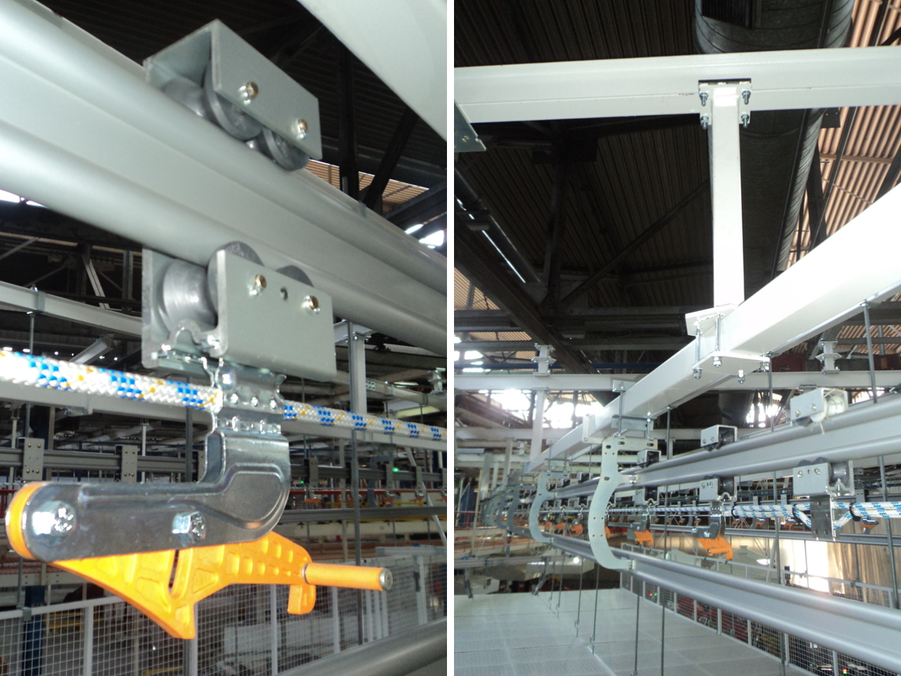
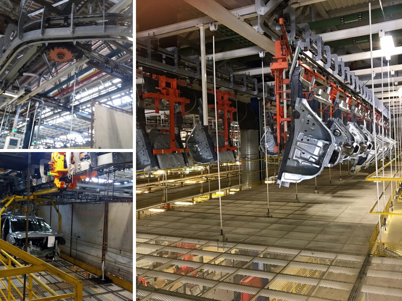
Power & Free
The Power and Free conveyor system is used to move parts and products in production areas across stations or in manual operations. Basically the Power and Free system has two rails one above the other. On the first rail, known as the “Power” rail, a conveyor chain circulates continuously while the conveyor is running.
On the second rail, the loads to be carried are attached to trolleys which move along the rail. Load bars connect 2 or more trolleys to build the hook assembly. Through trigger systems, the upper chain can push the hooks as required. In the eventual presence of hooks at the front, the trigger system disarms, allowing hooks accumulation in the line. In the hook assembly, loads are carried in holders, baskets or compartments. The hooks can also be opened to allow parts loading. Depending on the load to be transported, the system is available in 3, 4 and 6 inch rail configurations carrying loads up to 9,000 kg approximately.
The Power and Free transport system allows the parts to be idle or to move at variable speeds according to the needs, so the “Stop and Go” and “Assembly at Continuous Speed” production concepts can be applied. The typologies are “Overhead” or inverted (floor mounted).
The Power and Free system can be used in different production processes, equipment assembly, painting, welding, etc.
Main Features
- Robust system for heavy loads
- Low maintenance and complexity
- Operation in humid and high temperature environments
- High technical availability
- Simple technology with low automation rate
- Vertical and Horizontal Curves according to layout and process requirements
- Variable transport speeds