Applications

Multipurpose Line
Currently, most of vehicle manufacturers requires flexible lines, able to produce several models in a random mix, with future models integration in zero loss launch. This kind of approach requires to install complex equipment (turntables, trunnions, slides, etc.) starting from the first model, with large investments from the beginning. At the same time, these systems are quite inefficient, causing the overall efficiency of the lines to drop (due to low MTBF and very high MTTR). The footprint needs to consider the space required for logistics along the line (racks, manual loading/unloading operations, etc.), where all parts of all models must be available at the same time.
Due to the above reasons, most of car manufacturers are usually able to reach up to 4 models only, due to the available area in their plants. In addition, workers saturation rate is usually quite low, considering they need to wait robots and equipment to complete their sequences before starting the loading/unloading operations.
The idea of multipurpose line was born to solve all these issues, reducing the investment for the first model and the occupied area, improving line efficiency and workers saturation.
Main Features
- Batch production, using AGVs to replace fixtures/racks for model changing (meanwhile production is running)
- Lower investment for first model (the line is developed with a very lean structure, with AGV integration starting from second model)
- Higher efficiency, avoiding turntables, trunnions, slides or other complex equipment installed along the line for model changing
- Open to multi-model production, with no restriction for future model integrations
- Area optimization, dividing welding line and logistic (racks preparation/equipment stock) in specific areas
- Manpower higher saturation. Workers prepare all racks in a dedicated logistic area (supermarket kitting area), without been linked to welding line cycle time (no idle time)

MIG/MAG Welding
Arc welding is a very widespread form of welding. As the name suggests, arc welding uses an electric arc to melt materials before joining them together. A power supply is used to create an electrical arc between an electrode and the metal sheets to melt them together. This electric arc can create temperatures in excess of 3,500°C, which is high enough to melt metals such as carbon steel. The welding area is usually protected by shielding gas, steam or slag. This is because atmospheric air can interact with the weld pool and cause oxidation.
Both MIG (Metal Inert Gas) and MAG (Metal Active Gas) use a continuous solid wire electrode (welding torch), which is heated and fed into the weld pool from a welding torch. The two base materials are fused together, forming a joint.
The only difference between MIG and MAG is the type of shielding gas used (supplied through the welding torch). The composition of the shielding gas is important as it has a significant effect on arc stability, metal transfer, weld profile, penetration and spatter. MIG welding uses inert gases or gas mixtures as a shielding gas. Argon and helium or Ar/He mixtures are inert gases and are commonly used for MIG welding of non-ferrous metals such as aluminum. Inert gases do not react with filler material or weld pool. MAG welding uses active shielding gases. These gases can react with the transfer of filler metal through the arc and weld pool, affecting the resulting chemistry and/or mechanical properties.
MIG and MAG welding is the most common arc welding process in major industries such as automotive, railway, GI, among others. Between its main advantages we can mention:
- Suitable for high-speed welding with very high weld quality (allowing high production rate)
- Higher quality (compared to other arc welding processes)
- Versatile process that can be used to join a variety of metals and alloys
- Simple welding equipment (compared to other joining processes)
GME Expertise and Support
Bodies, off-road vehicles, trucks, trains, white industry, among others. All of them use welding processes based mainly on spot welding and MIG/MAG welding. Both require very strong specialization and technical ability.
GME has always performed a key role, supporting the main market players in the development of turnkey solutions. In particular, MIG/MAG welding requires special attention to the following items:
- Fixing plan – High temperatures reached around the weld seams may cause structural distortion in the final assembly. Therefore, it is very important to develop a suitable fastening plan, avoiding parts deformation during the welding process
- Welding spatter – During the arc welding process, it is quite common to see some weld spatter. In order to ensure a good quality of the welded assembly (also from an aesthetic point of view) and to avoid any problems in the subsequent processes (for example, the front cradle assembly process usually requires the addition of bushings with a high precision coupling process), the area around the weld seams must be covered to prevent weld spatter from coming into direct contact with the part
- Protection – Protect all cables from high temperatures and weld spatter, using a fireproof cover
- Seam locators/seam trackers for automatic arc welding – Robots are often used to improve quality and productivity, but it is necessary to ensure the repeatability and accuracy of all parts to be welded, to ensure the same result every cycle. This is not always possible in some industries (it would require very high costs), so the welding process must be adapted to different shapes and positions of the parts (within a certain range). Regarding arc welding, robots can be equipped with special sensors to check the position of the seam and correct its path during the welding process, detecting the displacement between the nominal and the real position at every cycle
- Healthy environment – A healthy environment must be garanteed, using air suction systems located at each welding operation and isolating all welding areas from workers’ eyes (with physical barriers or red curtains)
Co-design & Simultaneous Engineering
Besides the normal turnkey projects that GME usually carries out for its customers, it also develops processes that can be efficiently adapted to the characteristics of the product, considering the conditions of the production lines at the customer’s plant.
This activity, commonly called “co-design”, consists on the research and development of process solutions together with the customer, engineering and installation site, analyzing the new product features together with the real availability in the customer’s plant. In other words, a pre-validation on the measure that can be applied to a new process or retooling project.
The initial specifications for creating a co-design basically follows the sequence below:
- Process Mapping
- Logistics flow analysis
- 2D/3D Layout Creation for space definition
- Production Cycle Analysis
- Robots/Equipment Access Simulations
- Ergonomic and cycle time analysis
- Definition of equipment specifications
- Cost estimation and mapping
- FEM analysis
- Issue all technical specifications required for the project
In addition to the cost and time reduction, simultaneous engineering decreases the chances of having to modify the product at a more advanced stage due to unexpected problems. With regard to the project teams, the greater involvement between areas improves the commitment to the project as a whole.
GME usually works closely with the customer’s product department to develop cost-effective solutions. The car parts, clamping plan, process, and all the items involved are evaluated to optimize the result, based on the experience of GME team through the years.
.
Case Studies
Case 1
- Up to 30% reduction in investment
- New model developed in conjunction with manufacturing engineering
- Customer technical specifications developed together with GME team
Case 2
- Up to 40% reduction in investment
- Common GEO devices
- Common RESPOT devices for various models
- Common grips for various models
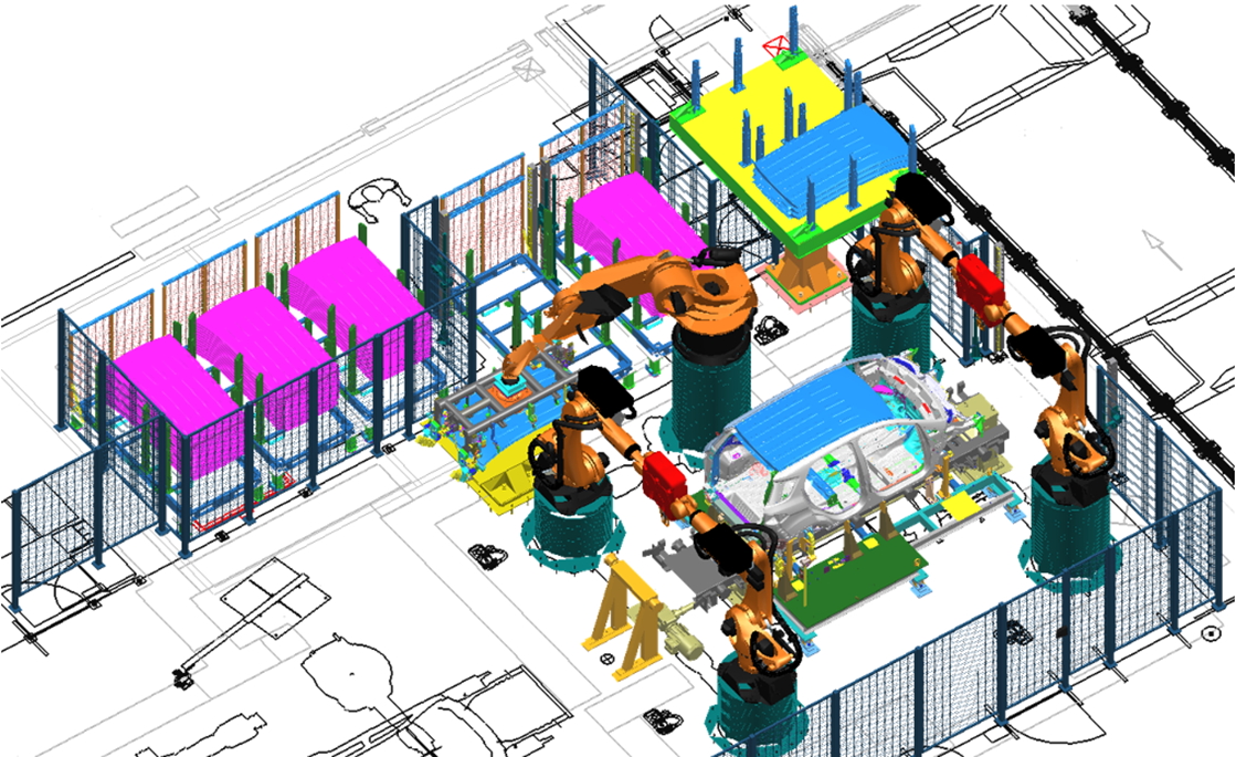
Free Expression
The name “Free Expression” is due to a challenge defined by our main customer, where all competitors were “free” to develop a new proposal for Front and Rear Doors line, without any kind of restrictions in terms of layout.
GME proposal was selected as the best one, introducing a new concept where both right and left sides are produced in the same line.
Savings compared with a traditional solution:
- Robots: -30%
- Integrated machines: -50%
- Sealing systems: -50%
- Manpower: -30%
- Occupied area: -30%
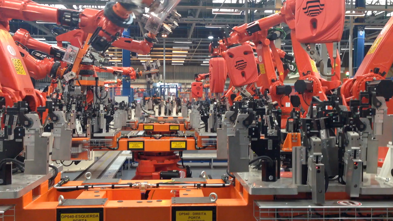
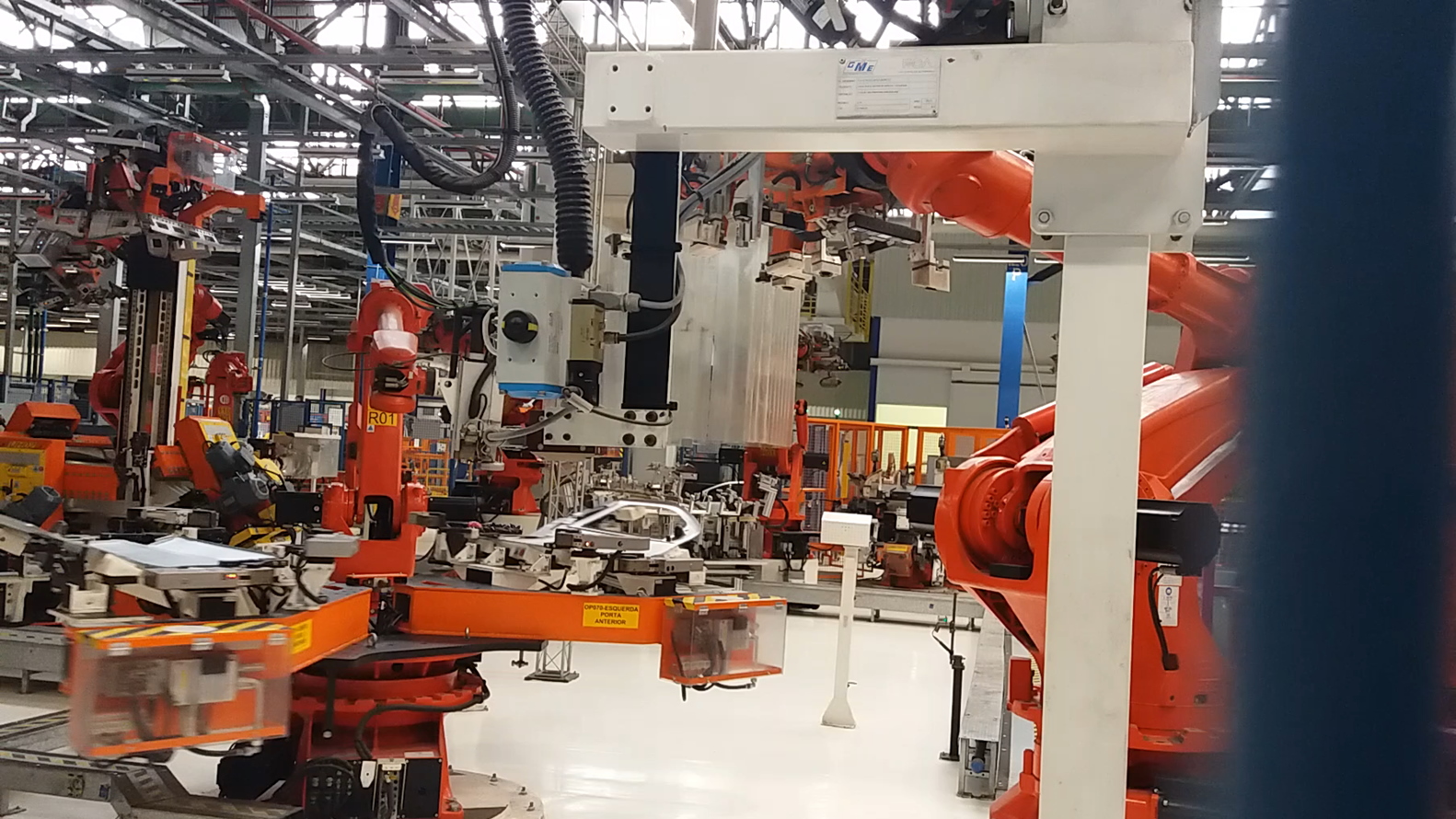
Main Features
- Handling and welding sides are completely divided, avoiding idle times, so that all robots can reach the maximum saturation rate (over 90%)
- Meanwhile welding robots are working on the right part, at the opposite side of the turntable, the left parts are loaded/unloaded by handling robots
- Welding guns, sealing systems, integrated machines, handling robots, etc. are totally shared between right and left parts
- Manual loading of both parts (right and left side) where possible, maximizing workers saturation rate (over 90%)
Technical Features
- Production rate until 66 JPH (132 parts per hour, 66 right + 66 left)
- Technical efficiency: 92%
- Batch production
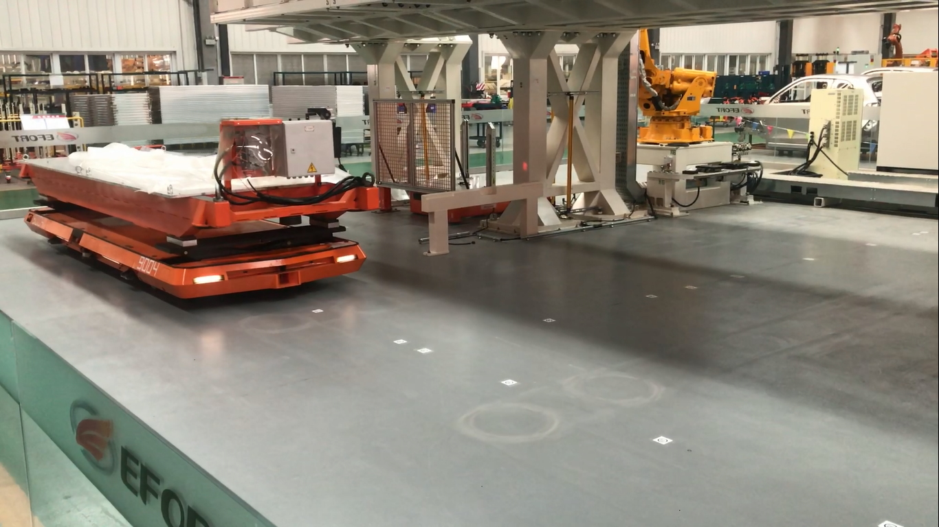
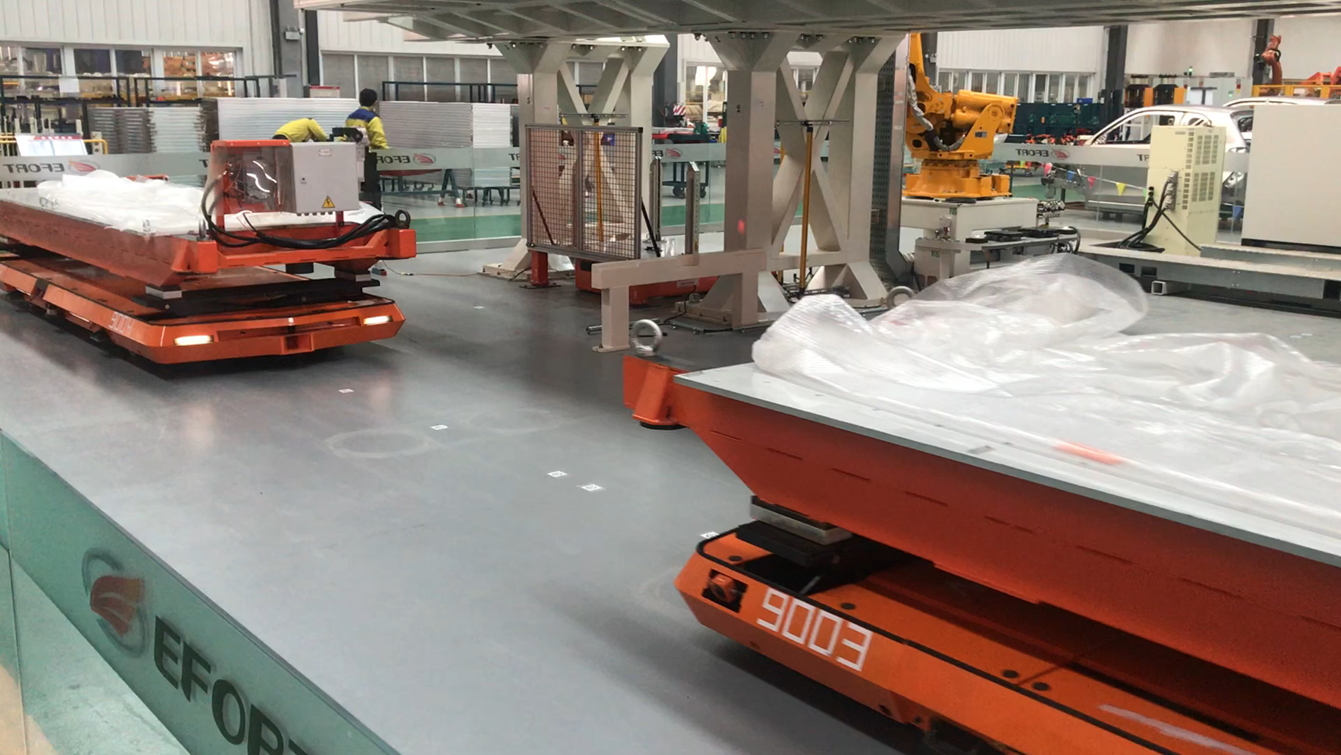
Automated Guided Vehicle
Automated guided vehicles, or AGVs, deliver greater efficiency and safety in warehouses, distribution centers and industrial environments in general. Its versatility allows the transport of different types of products between different points, such as between warehouse and production or delivery of final product and stock.
Through a 2D “QR Code” reading system on the floor and exchanging information through a dedicated set of antennas, its programming allows the vehicle to know exactly where the cargo is and its destination, with wide movement flexibility in the most diverse environments. Its construction allows the use of an elevating and rotating platform, providing the possibility of changing the product orientation between the pick-up and delivery point, ensuring even more flexibility to the logistics system of your company.
The vehicles have a dedicated battery and their charge management defines the moment of self-charging, without the need for intervention by your company’s logistics or maintenance team.
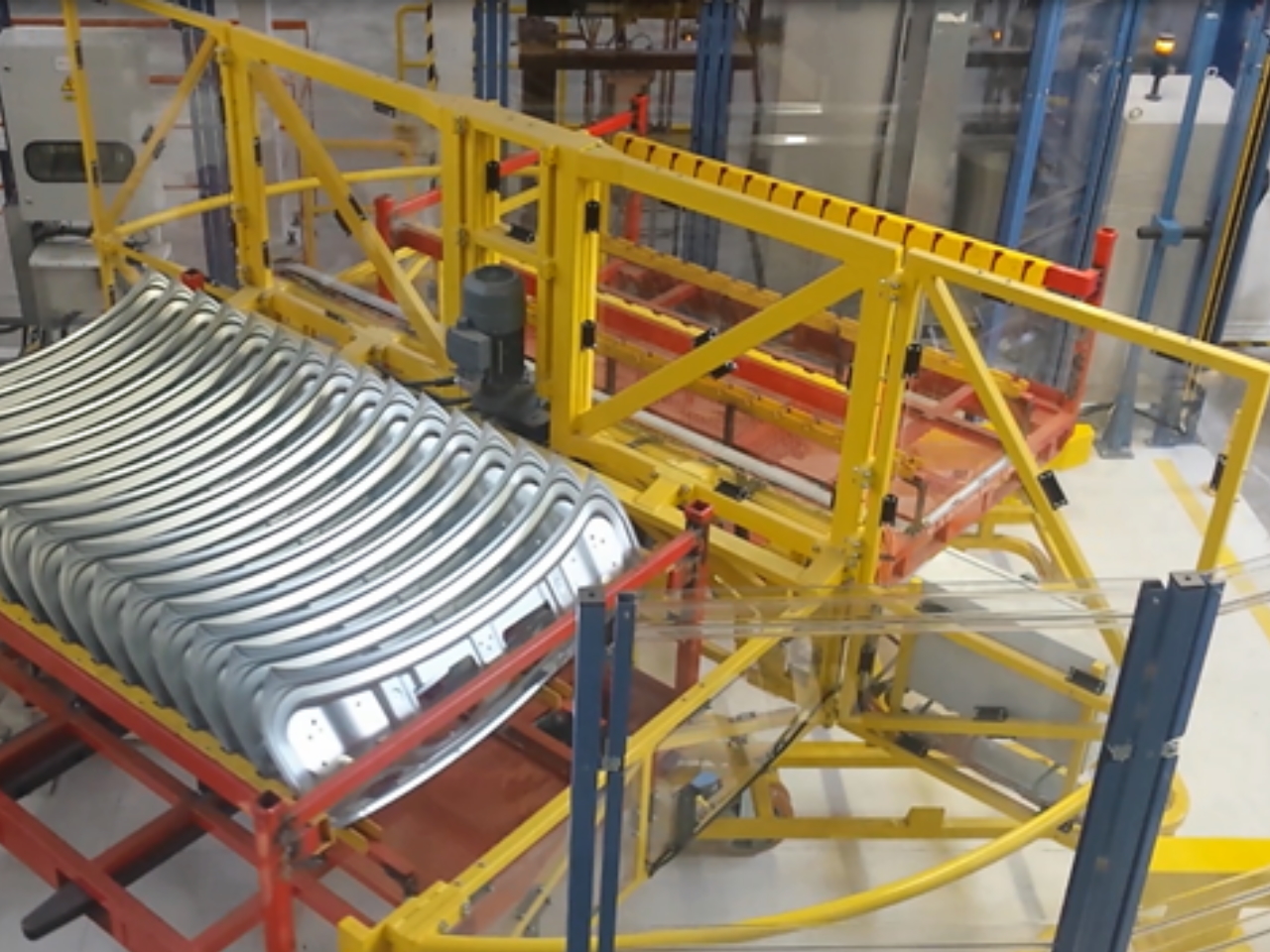
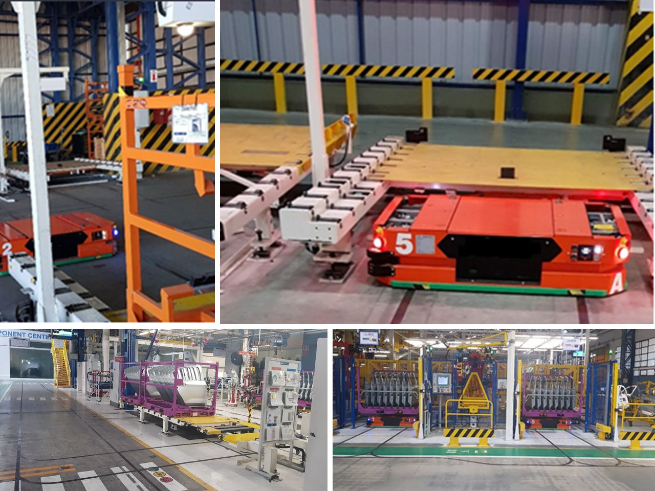
Application example (case study)
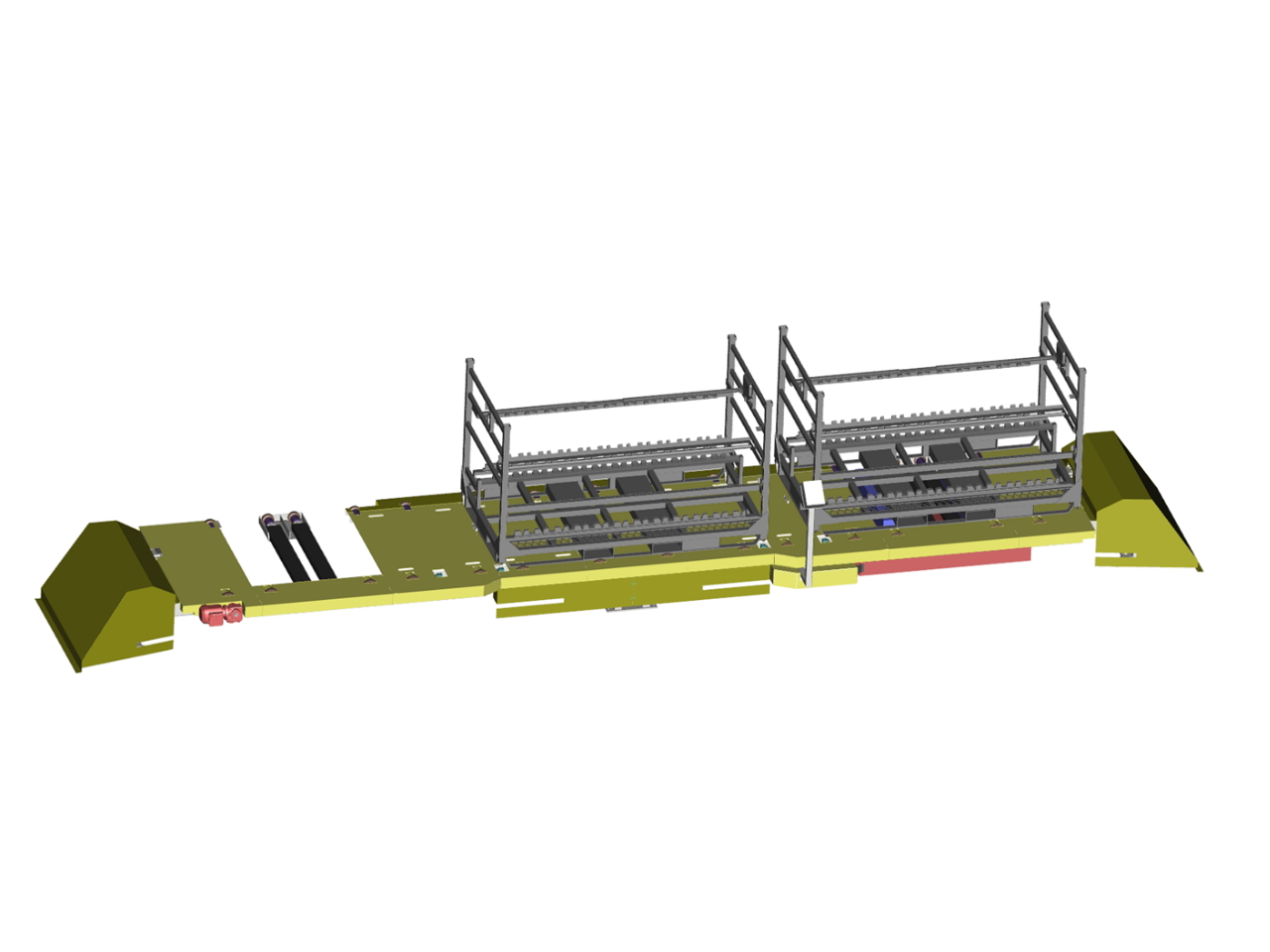
The AGV-driven rack transport system enables parts and/or product racks to be delivered line-side cyclically without the use of operators.
Through a parameterized trajectory system, it is possible to predetermine the path to be followed in the plant aisles, allowing the entire flow of materials to be automated on the ‘line side’. Using flow simulation tools, it is possible to determine in advance whether the designed system will be able to meet the required line cadence, including simulating all line-side logistics.
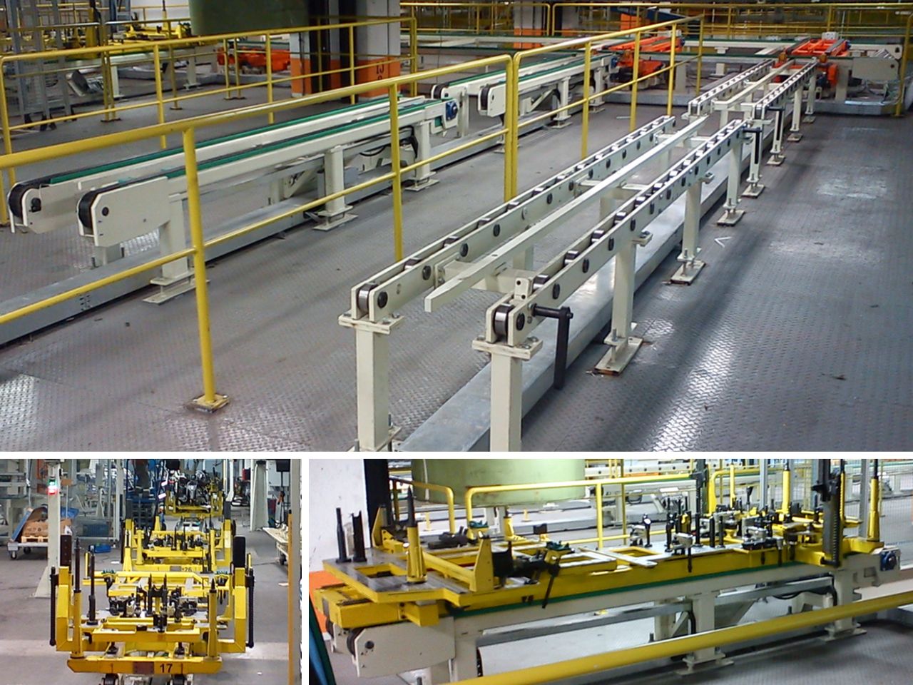
Racks can be loaded by forklifts using a roller table system, or directly on the robotic island automatically. In the unloading area, products are preferably stacked in order to have a suitable working buffer. Racks are placed at an ergonomic height to allow the operator to pick up parts.
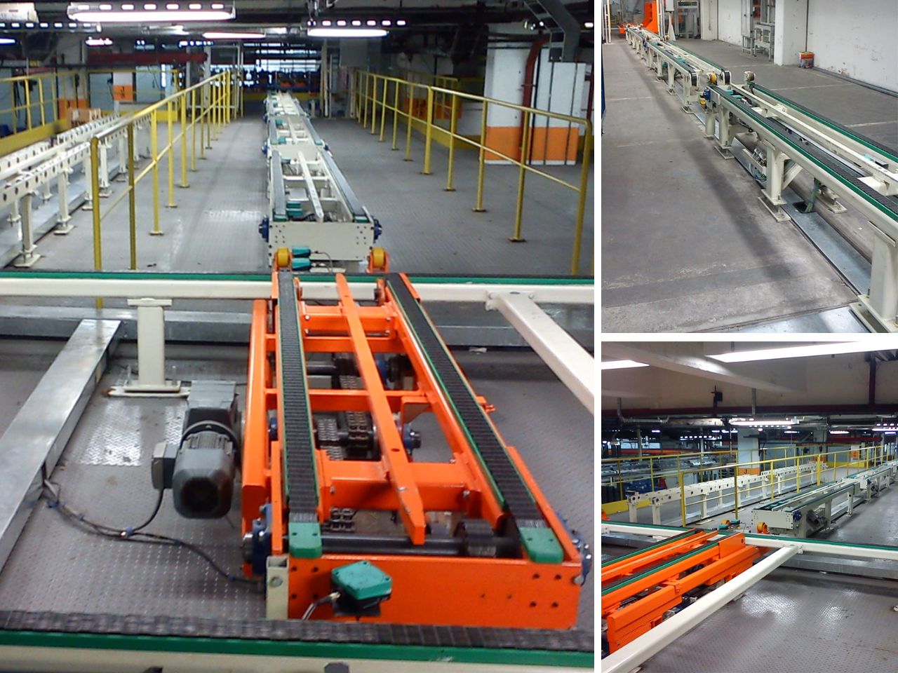
AGV Auto Load
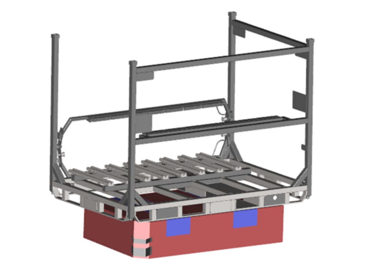
AGV
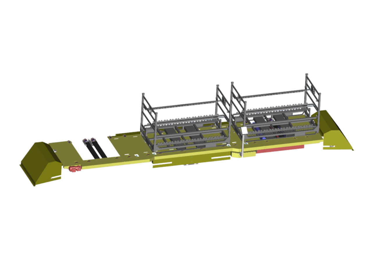
Line-side Unloading
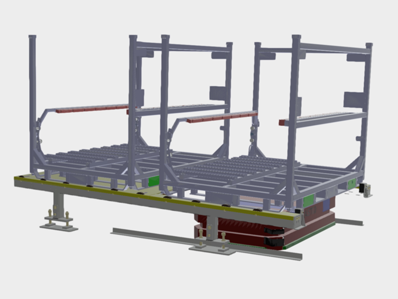
AGV Manual Loading System
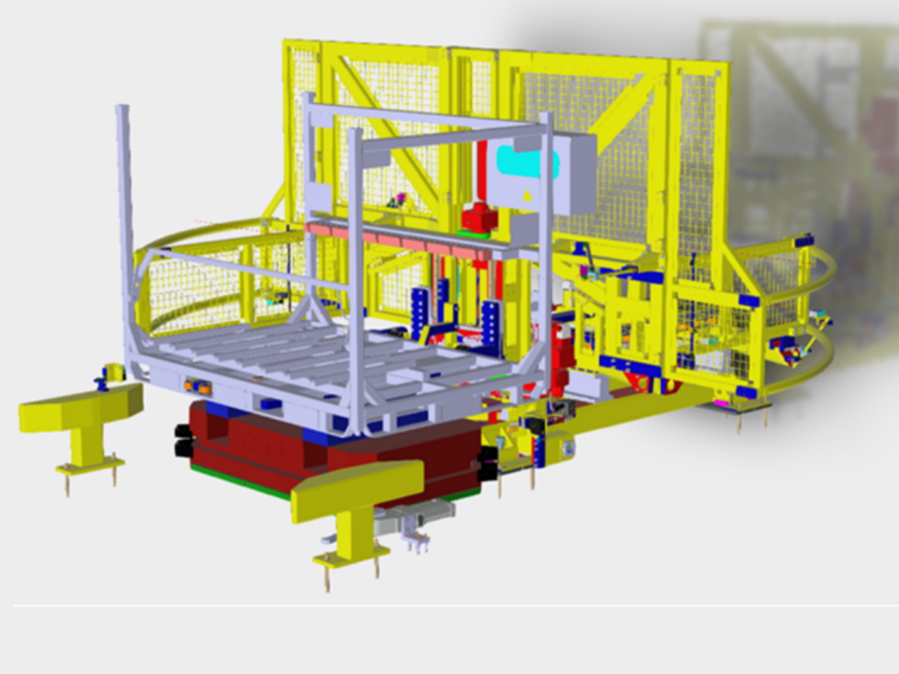
AGV Automatic Loading System
Line Side Rack Storage System
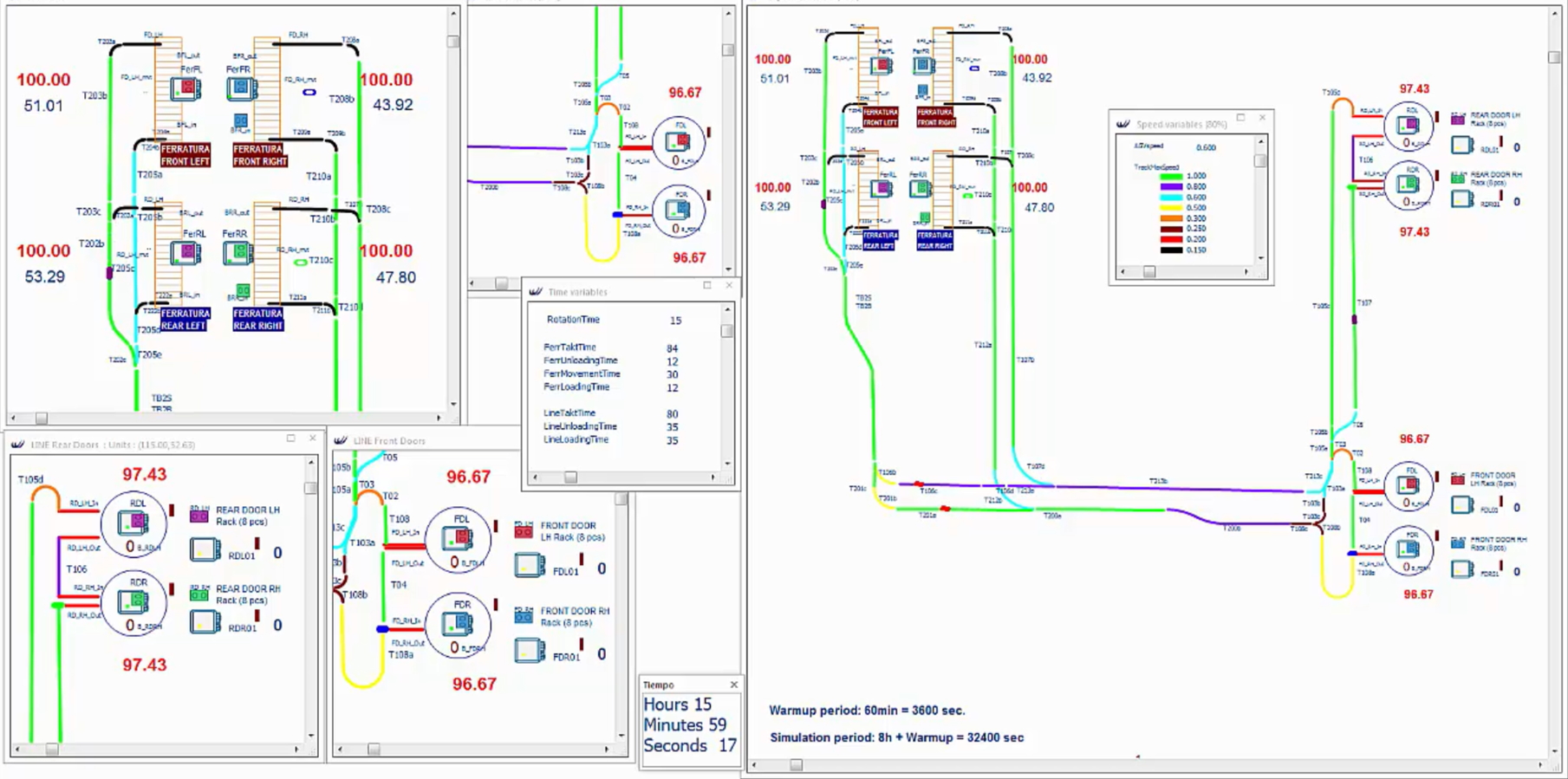
Virtual Flow Simulation AGV Circuit
Main Features
- Lifting stroke: up to 100 mm
- Payload: up to 1000 kg
- Handling speed: up to 1.2 m/min
- Lowest conveyor level: 35 0mm
- Surface treatment: Painted
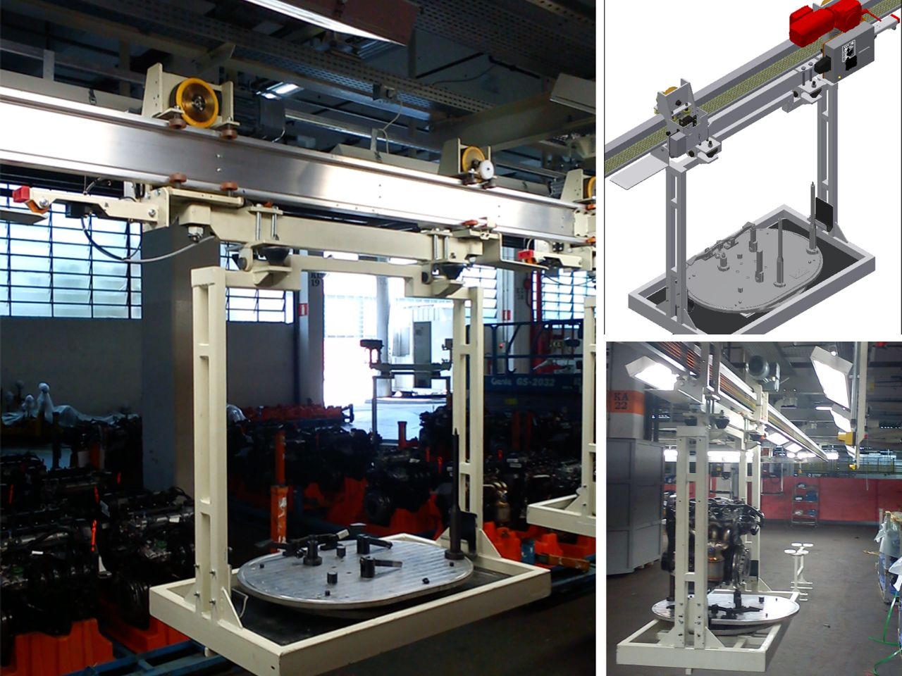
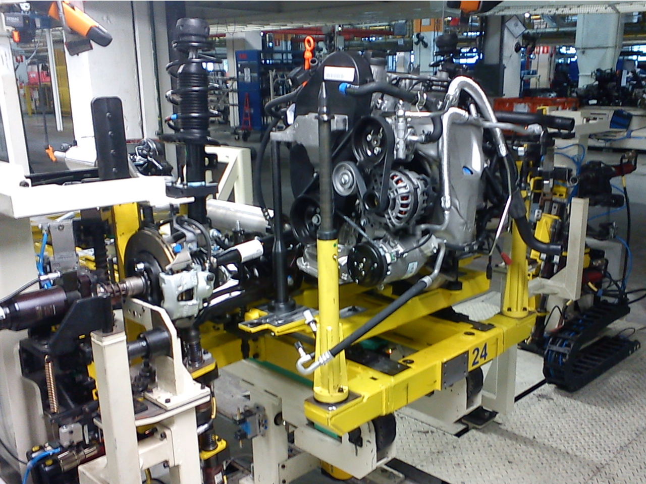
Fahrwerk - Marriage between Body and Powertrain
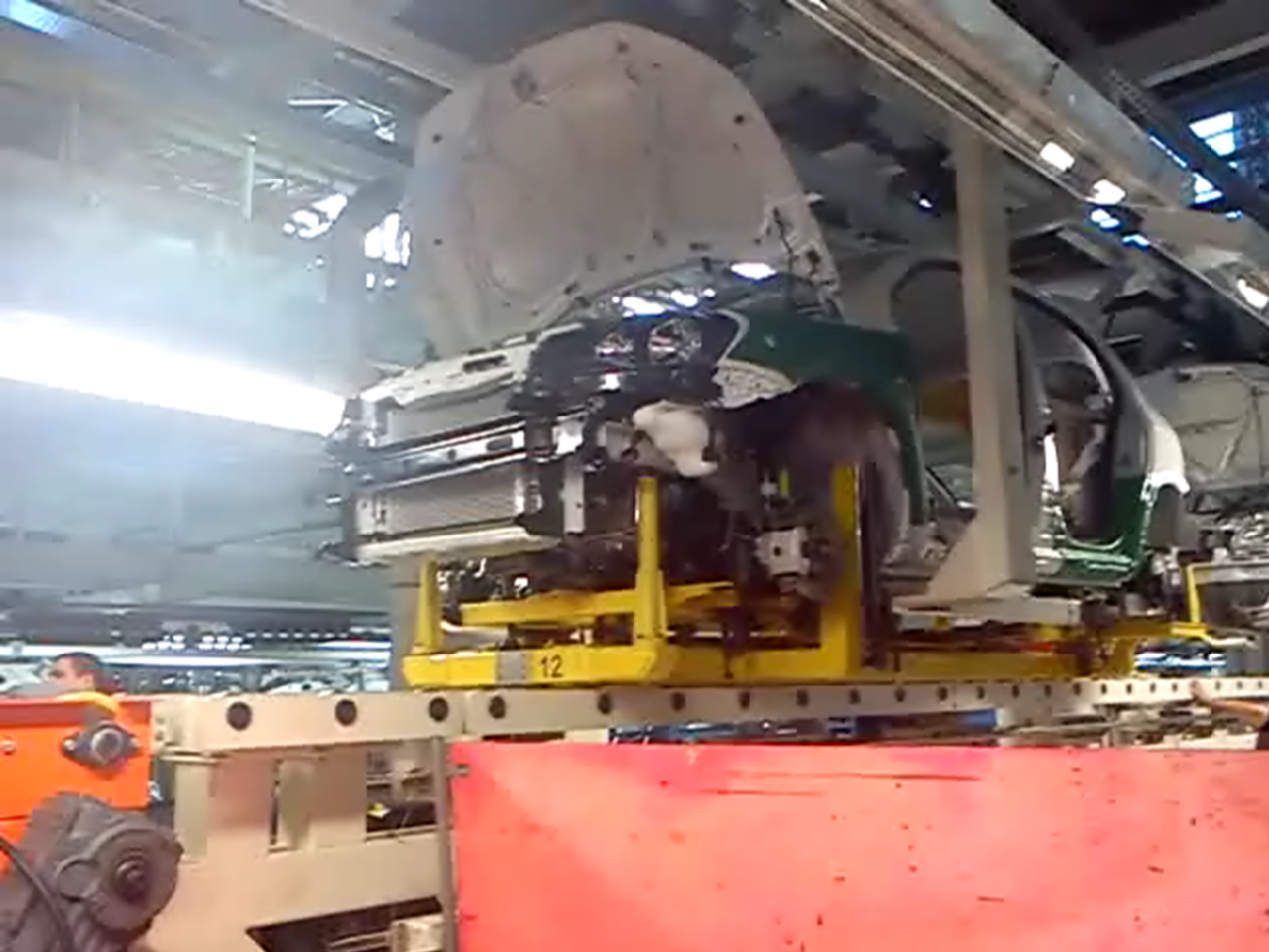
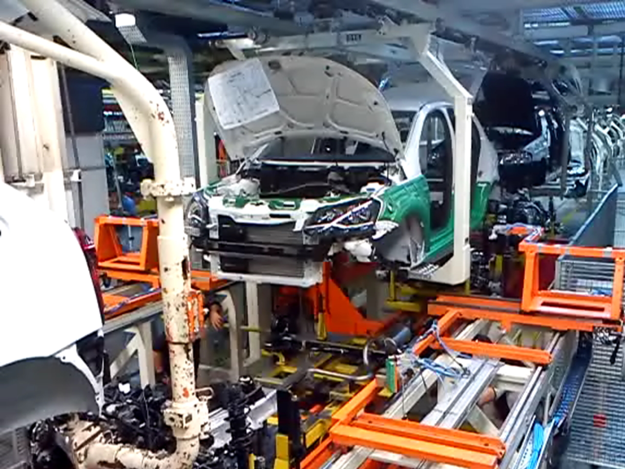
In the final assembly there is a station where the body and the powertrain are joined in a synchronized way, this is known by manufacturers as “marriage”. It consists of a precise, fast and synchronized process where a few dozen screws are tightened and in a few seconds the body finally gets its powertrain set (engine and transmission).
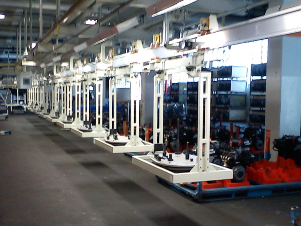
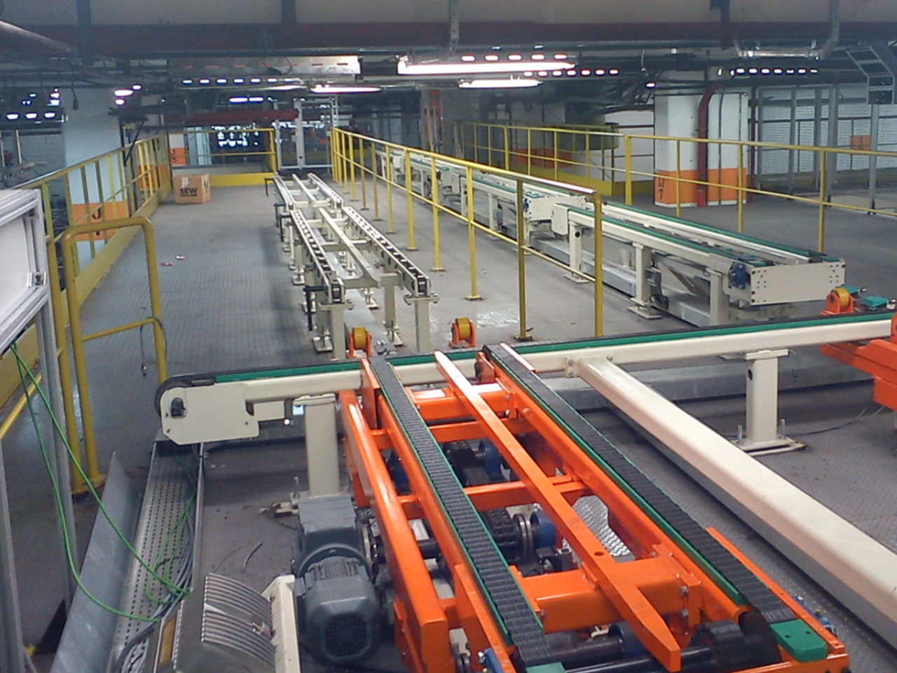
The powertrain assembly starts with the assembly of engine accessories (hoses and belts). Most of the screws are performed with automatically controlled torque. After the engine is assembled, the powertrain set is mounted on a special assembly plate, which is transported on roller tables. The plate is transported through different stations where step by step the porwertrain system is assembled. The powertrain consists of the engine, gearbox, axles, transmission, exhausts, shock absorbers, among others. The body normally comes on an overhead conveyor with its interior assembled.
Finally, in the marriage, the suspended body is positioned on the plate containing the powertrain assembly, here the synchronism of speeds between the overhead conveyor and the roller table that contains the powertrain assembly plate takes place. At the same time the transfer speeds are synchronized (powertrain and body), the powertrain assembly plate table begins to lift until it engages the assembly with the body. At the next stations, the components are bolted to the body, then the assembly plate is uncoupled, leaving the body and powertrain together being transported by the overhead conveyor.
Technical Features Engine Assembly
- Engine assembly stations: 14 stations
- Engine assembly EOM Air Conveyor Length: 500 meters, 2 elevators
- Speeds: from 0.5 m/s to 30 m/s
- Cycle times: as required
- Torques with automatic screwdrivers
Technical Features Powertrain Assembly Plate
- Powertrain assembly stations: 14 stations
- Powertrain plate assembly conveyor: 15 roller tables, 3 elevators
- Speeds: from 0.5 m/s to 25 m/s
- Cycle times: as required
- Torques with automatic screwdrivers
Technical Features Marriage System
- Body Transport Air System: 50 meters Power&Free
- Powertrain Plate Transport System: 2 lifter roller tables, 10 roller tables
- Speeds: from 0.5 m/s to 25 m/s
- Cycle time: as required
- Torques with automatic screwdrivers
- Automatic (robot) or manual screwing
- Coupling control with vision system